From the very beginning, the Chinese Theatre has striven to give the public the best possible show. Part of this experience includes the projection room. From the silent era to IMAX®, the Chinese has played host to the entire range of motion picture technologies. This heritage is so illustrious, that a history of projection and sound reproduction systems is a long and complex tale. We welcome readers to help flesh out this history, as it, while fascinating, is a most elusive subject.
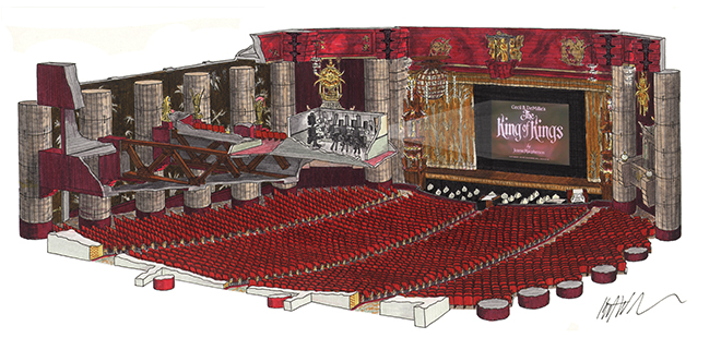
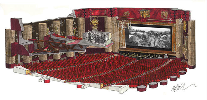
The Chinese auditorium was originally nearly 100 feet square; from the footlights to the back wall, it is divided structurally into 7 bays of roughly 17 feet each. The "Cathay Lounge" overhangs two of these bays, and so if the screen is somewhat beyond the footlights, the projection throw is around 90 feet. The 1.33:1 screen was probably 24 feet wide by 18 feet tall. It may have been smaller. 24' x 18' might seem tiny by today's standards, but in the 1920s even at the deluxe presentation houses like the Chinese, the picture sheet size was kept small in order to provide the brightest and sharpest picture possible. A projection beam 85' x 24' is three and a half times as long as it is wide, which is pretty narrow. The smaller the picture, the longer the focal length of the projection lens, resulting in a greater depth of focus. Compare this throw with that of today's IMAX® projectors, which must fill out an image 87 feet across with a 106 foot throw. That is only one and a quarter times as deep as it is wide, making it far more of a challenge to keep the image on screen sharp and evenly illuminated.
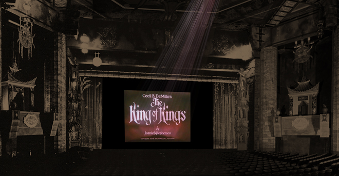
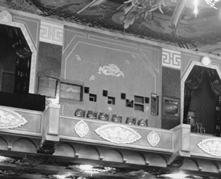
Grauman's Chinese Theatre, Hollywood, California. Auditorium showing position of projection room and 1:1.33 screen 18' x 24', 1927. Drawing by Kurt Wahlner.
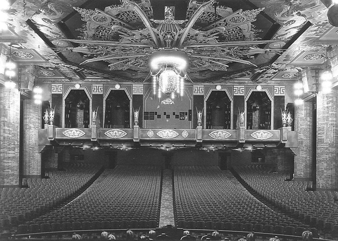
Grauman's Chinese Theatre, Hollywood, California. Auditorium from the stage, 1927. Photographer unknown. From The American Architect, August 20, 1927, page 252; "Chinese Theatre at Hollywood, California" The Architectural and Building Press, Inc., New York City. Courtesy of Kurt Wahlner.
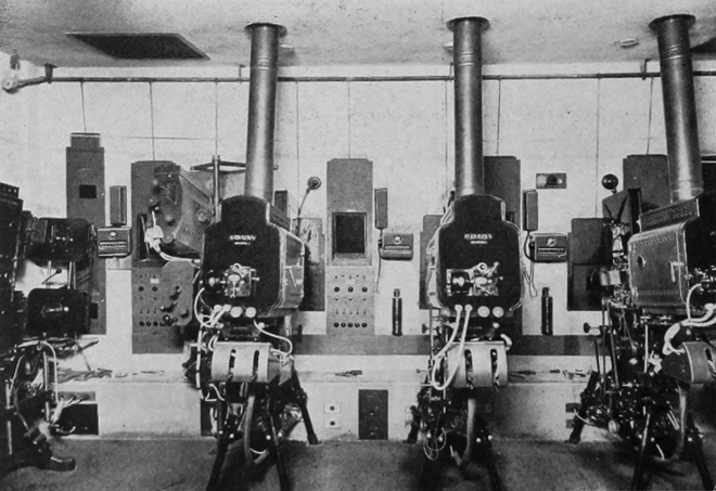
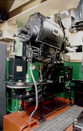
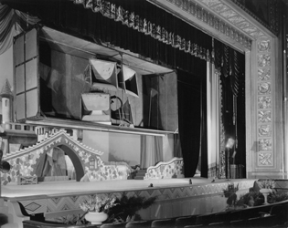
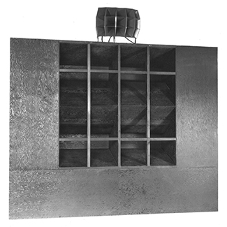
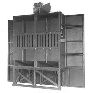
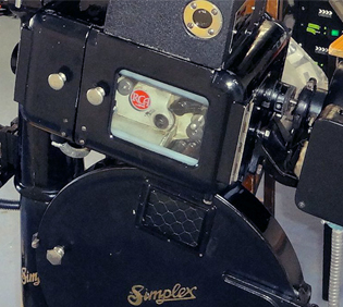
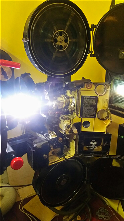
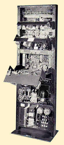
Sid Grauman, outfitting his Chinese Theatre, had in mind only one thing: The best of everything. Originally, the projection booth was situated upstairs in the center of what came to be called the "Cathay Lounge." The booth was 17 feet deep by 28 feet wide, and 9 feet tall. It was equipped with three Powers 6B Improved projectors, a Brenkert Slide / Effects projector, along with probably a pair of follow spots: one a Brenkert, the other, an unknown make.
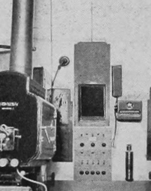
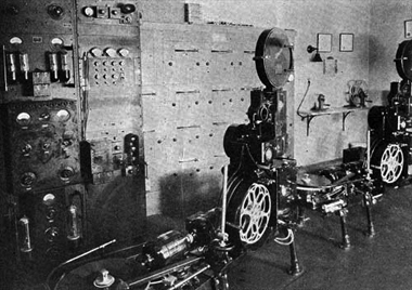
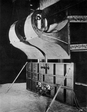
Grauman's Chinese Theatre, Hollywood, California. Projection Room, 1928; photo probably taken during the 1927 run of The Gaucho. Photographer unknown. From Motion Picture News, February 4. 1928, "Brains and Arms of Showmanship in Phone Link" by Carl. J. Begemann. Motion Picture News, Inc., New York City. From left to right: Brenkert effects projector; two pole-mounted follow spots, the upper a Brenkert Type C3, the lower unknown; Powers 6B Improved projectors with Ashcraft lamphouses.
The booth contained all of this projection equipment in a somewhat small space. All of the projectors at this time utilized carbon-arc lamps as their light sources. Carbon arc lamps had been in wide use since the 1890s, and were used in motion picture projection into the 1970s. Brilliant light is produced when two carbon-rod electrodes are touched together and ignite, creating what is called an arc discharge — an arc of light jumping between the two electrodes. The carbon rods burn away during this process, so in every lamphouse the carbon holders are controlled by worm gears in an attempt to keep the carbons at the correct distance from each other as they burn up.
This form of light was preferred not only because of its brightness, but as DC electricity was essential to the set-up, it produced a non-flickering light, which was crucial to the task of getting light though film frames passing through the gate with the shutter open at less than 1/50th of a second.
The carbon arc lamps produced a great deal of heat, as well as smoke from the burning carbons, and so the lamphouses were insulated so that the operators would not burn themselves, and they were always equipped with exhaust chimneys with fans to carry away the heat and carbon smoke.
Movies at this time were shipped to theatres on 1,000 foot reels of 35mm nitrate film. Often, two 1,000 foot reels were spliced together, making a 2,000 foot reel, which over time, became the industry standard. A 2,000 foot reel is slightly more than 20 minutes worth of footage, and thus a 90 minute feature would be on 5 reels. One would run the first reel, and then "change-over" to the next projector, which would run the second reel and so on to the end. The Chinese had three projectors installed, with the theory being that if one projector broke down for whatever reason, the show could still go on, as two functioning projectors remained. Making change-overs was a complex process, as both projectors had to have their arc lamps lit, and one projector's "douser" had to close at the end of one reel, while the "douser" on the next projector would open at the beginning of the next one; all the film had to be in the correct position for all of this to happen, complicated by the fact that the projectors started slowly and took time to get up to speed and so on.
Naturally, a change-over could not be done by one person by hand without it looking funky, so several companies began to make "automatic dousers" which controlled the set of projector dousers electronically. Only one douser could be open at one time. As a reel came to its end on machine #1, the operator would wait for a cue mark, seven seconds from the end of the reel. This was the cue to start the motor on machine #2.
Then, just as the reel on machine #1 ends, another cue mark appears. This is when the operator would press the button for the auto-douser, and BANG! the douser on machine #1 would close, the douser on machine #2 would open, making the change-over on the screen look like a straight cut. Most people don't notice the cue marks. The Chinese was undoubtedly outfitted with the "Weaver Auto-Douser" for reasons which will become clear below.
Grauman's Chinese Theatre, Hollywood, California. Projection Room, Fire Shutter Detail, 1928; photo probably taken during the 1927 run of The Gaucho. Photographer unknown. From Motion Picture News, February 4. 1928, "Brains and Arms of Showmanship in Phone Link" by Carl. J. Begemann. Motion Picture News, Inc., New York City.
All motion pictures were released to theatres on 35mm cellulose nitrate film, which was an unstable and highly flammable material. The main reason films from this era are "lost" is due to theatre fires, along with negatives and prints decomposing. With the invention of cellulose acetate, or safety film, in the late 1940s, things became a good deal safer, but before then, all theatres had to pay extra special attention to the fact that the print up in the booth, being passed in front of a VERY hot flaming light source, could catch on fire!
So the Chinese, as were all projection rooms prior to 1950, was outfitted with fireproof shutters raised over each and every port window. Each of the shutters was held aloft by a chain with a ring at the top, which slipped around a rod spanning the width of the booth, with all of the shutters attached. If the operator tripped any one of the shutters, the chain would tug at the rod, and all of the heavy shutters would close with a crash, sealing off the windows as an escape path for a fire.
Hollywood is part of the City of Los Angeles, whose Building and Safety Department required each theatre in the city to not only have this equipment, but to be inspected and licensed every year. This licensing was required until 1980 or so, when automation systems made everything a good deal safer.
At the opening of the Chinese in 1927, all technical aspects of the theatre were under the supervision of the Technical Director, George Ormston. Under him was Edward Keller, who was the Head Projectionist. Union rules required that there be two projectionists on duty at any performance, and so, in addition to Mr. Keller, there were probably five others under his supervision. All of these projectionists were members of the IASTE, the theatre technician's union. It is unknown what their pay scales were. Each man in the booth would work a matinee shift or an evening shift. Grauman's "Midnite Matinees" held in 1929 and 1930 would hold over the evening crew, who would receive overtime for working the late performance.
Grauman was too much the gentleman to suffer the projection staff to have a toilet in the booth itself, as was the case in many theatres. The Cathay Lounge overhanging the orchestra floor was equipped with both a ladies and a gentlemen's restroom, along with storage, a conference room, and Mr. Grauman's office.
The Powers Projector
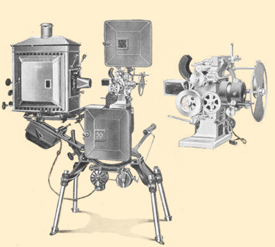
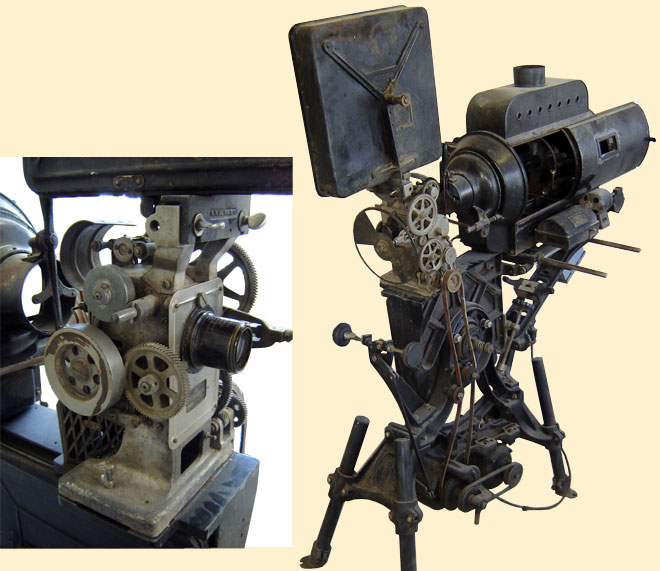
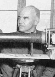
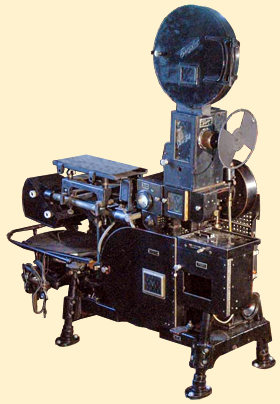
Powers 6B Improved Projector, from A Brief Description of Powers Projectors and Accessories catalog, issued by the Nicholas Power Company, Inc. No Date, probably 1926 or 1927. Projector 78" in height, 60" in width, 26" in depth. Shown with Powers-made Type "E" Lamp and Lamphouse. Note the lack of a sound head. Scan courtesy of Soterios Gardiakos.
Sid Grauman had been purchasing Powers Company projectors, probably since they started making them in 1902. The 6B "Cameragraph" model had been manufactured since about 1923. By 1927, the 6B had been "Improved" and so this was now the model name which went into the Chinese.
This projector had a number of interesting features:
Although electrically powered, the 6B Improved projector allowed for hand-cranking.
The main crankshaft connected to a speed indicator.
Inside the gate, there was a "framing lamp" shining light from behind the gate, which helped the operator to place a film frame correctly on the gate.
The shaft in the take-up magazine was of a ball-bering type, lubricated with Vaseline.
The lens mount contained a rack and pinion double-sided focusing knob, allowing the operator to focus from either side of the machine. Lens were held in place with set screws and adaptor rings, allowing for differently sized lenses.
The Loop Setter, which consisted of moving rollers under the gate, correcting the lower loop when bad splices cause the loop to become too tight.
Powers sold Bausch & Lomb "Cinephor" lenses to go along with this machine; for the Chinese, it was probably a 3.25 inch lens.
The stand had a pivoting device, which allowed for the projector head, magazines and lamphouse, to be tilted to the angle needed (at the Chinese this would have been nine degrees), but there was a worm gear included, which allowed for finer adjustment.
The distinctive rounded-corner upper and lower magazines could hold 1,000 foot or 2,000 reels. Catalog copy indicates the reason for this: with rounded-corner square magazines, it would be easier to grasp a reel and remove it, than it would be with round magazines.
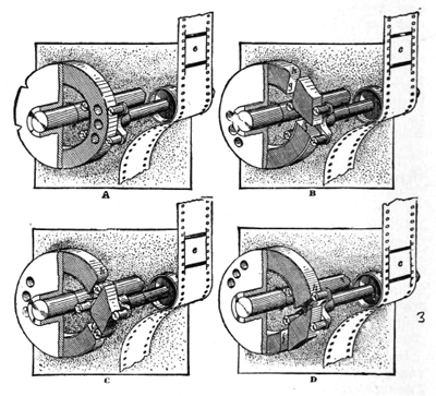
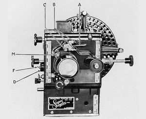
The heart of any projector is its intermittent movement. An intermittent transforms continuous rotation from the motor into the stepping, advancing-the-film-one-frame-at-a-time while flashing light through the frames at the right moment, motion.
The Powers projector had a very unique intermittent, which they called the Roller Pin Intermittent. It is somewhat obscure, but the diagram shows how a cam with a diamond-shaped cutout along the edge, would come into contact with a four-fingered claw attached to a sprocket with the film. As the cam turns clockwise, the diamond would come into contact with the claw, giving it the proper shove to the shaft with the sprocket, pulling the next frame of the film into position.
The whole assembly was encased in oil, and it was recommended to replace all the oil in the intermittent well every month. The Nicholas Power Company suggested that only their own specially-formulated brand of oil be used with their projectors.
Powers 6B Improved "Roller Pin" intermittent diagram. From Richardson's Handbook of Projection: The Blue Book of Projection, Fifth Edition, Volume 2, page 694. By F.H. Richardson. Chalmers Publishing Company, New York, 1927. Courtesy of the Internet Archive, scanning and archiving sponsored by Jeff Joseph.
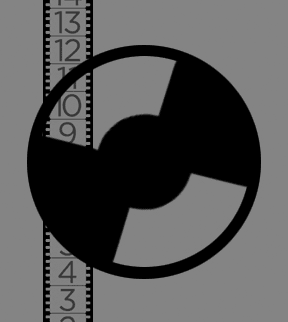
The slotted disc in front of the lens is the projector's shutter. While the intermittent pulls each frame into position before the gate, the shutter cuts off light to the screen while the film is advanced. In order to try to reduce the "flickering" which was very noticeable in the hand-cranked days, the shutter was designed with two openings for each revolution. And so each frame was exposed twice, resulting in double the number of flashes on the screen with the same number of actual frames.
Projectors have utilized this technique since the beginnings of projected films, and many film projectors today utilize this design, along with a small coterie of video projector buffs who are installing practical shutters like these in order to smooth out 3D images projected digitally.
Typical silent projector shutter diagram, showing the "double exposure" method made possible with the two-opening shutter.
The armature rising up in front of the projector might look like a focusing knob, but is actually a speed controller, connected by belts to the motor at the bottom. This was a design feature of the Powers machines for some time, as during the silent era, with its sometimes hand-cranked cameras and live musicians providing musical accompaniment, speeding the film up or slowing it down was always desirable. It has been documented that some of the really huge deluxe houses actually had a speed controller on the conductor's desk in the orchestra pit, but it appears that the Chinese did not have this feature. Richardson's Handbook of Projection 5th Edition from 1927, makes mention of the speed indicators available for the projectors, which could be located in the orchestra pit as well as the manager's office.
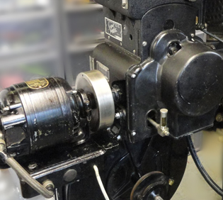
Powers 6B Improved projector, Peerless lamphouse, and Bausch & Lomb lens at the Grand Canyon National Park Museum, gift of Leo Atherton and the Williams-Grand Canyon Mason Lodge. National Park Service Photos.
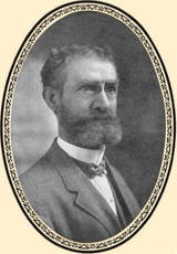
Nicholas Power (1854-1921), was born and subsequently found himself on his own in New York City. Interested in magic lanterns and mechanical devices, he was taken on as an apprentice mechanic at the age of 13. He attended the Cooper Union Institute, graduating in 1870. For many years Power worked in the mining industry, but this did not prevent him from dabbling with magic lanterns for various applications. In 1897, Power got a job as projectionist at the Novelty theatre, a nickelodeon in Brooklyn, where he took apart all the projection equipment and put it back together. He was hooked.
Nicholas Power. Unknown date. From Powers Cameragraph Projectors: A Reclassification by Soterios Gardiakos, Aurora, Illinios, 2013.
After watching Edwin S. Porter attempt to start a projector company, Power opened a projector repair shop, eventually making his own brand of projector, the Peerless-scope by 1898, then changing the name to the Powers Cameragraph in 1902. They sold well, finance was there, and a factory was built at 88-90 Gold Street in New York City (where Pace University now stands). Their company motto was "Better Projection Pays."
Ad appearing in the Motion Picture News, "Buyer's Guide Section," June 24, 1927. Motion Picture News, Inc., New York City.
Several models of the Powers Cameragraph were introduced, and proved to be very popular. Power died in 1921 while on vacation in Florida. While his widow, Rose, sold the company in 1925 to the International Projector Corporation (owners of the Simplex brand), the Power brand continued along until sometime in the early sound era.
The Weaver Auto-Dowser
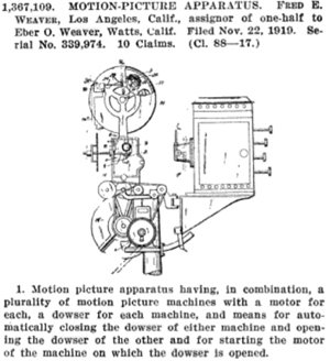
Here is an interesting story. Back when films were one or two reels only, projectors were shipped from their factories with a hand-operated douser. Open the douser, light would flow from the lamphouse through the film gate and projection lens, and onto the screen. When multiple reel "feature length" films were becoming the norm, the Weaver Brothers, Fred, along with his brother Eber, developed an electrically controlled douser which could be installed inside any make of projector.
The advantage of this was simple: as one comes to the end of a reel, the operator would see the first cue mark, then start the motor of the next projector loaded with the next reel of the picture. Then, the operator would wait for a second cue mark, marking the end of the reel. One would hit the button on the Weaver Auto-Douser, and the solenoids attached to the dousers would connect, instantly closing the one and opening the other.
Other companies entered into this niche market of making third party dousers for projectors, while the projector manufacturers continued to ship out product without this feature, figuring that the theatre owner would buy electric douser controllers from one of these third party companies, since a given theatre might have two, or three, or even four projectors in the booth.
Records indicate that Fred and Eber capitalized their company to the tune of $15,000 in November of 1921, with a manufacturing facility in the Watts area of Los Angeles. The Weaver Auto-Douser was sold up to the end of the multiple-projector era, in the late 1970s. The Weavers also developed a motor controller for theatre curtains.
U.S. Patent No. 1,367,109 issued to Fred E. and Eber O. Weaver for an automatic douser controller. From U.S. Patent Office Gazette, February 1, 1921.
ABOVE: The Weaver Auto-Douser mounted on a Simplex Standard projector. Unknown film clip from Projection: 85 Years of the Projection Booth in Movies by Joseph Holmes, on Vimeo.
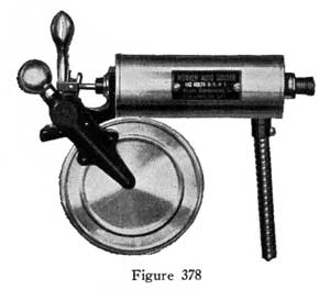
LEFT: Weaver Auto-Douser. From Richardson's Handbook of Projection: The Blue Book of Projection, Fifth Edition, Volume 2, page 959. By F.H. Richardson. Chalmers Publishing Company, New York, 1927. Courtesy of the Internet Archive, scanning and archiving sponsored by Jeff Joseph.
Fred E. Weaver became the Head Projectionist at the Chinese by 1930. Mr. Grauman must have recruited him for his obvious commitment to improving the quality of projection. Because of this development, it is safe to say that the Chinese booth was equipped with the Weaver Auto-Douser.
Weaver was born July 11, 1889 in Kansas. He was not formally educated. He and his girl, Rose, married when he was 19, then they had two children: daughter Francis in 1910, and son Bill in 1913. The family was in Los Angeles by 1919, with the Weaver Auto-Douser Company starting in 1921.
It is interesting to understand the economic dynamics of this period. Weaver had a wife, two children, and was part owner of a successful company. By the time he went to work at the Chinese in 1929-1930, he was living in an apartment on Kings Road, and they had taken in a border. Different times. Weaver continued to work on theatrical inventions up to his death on March 21, 1962 in Compton.
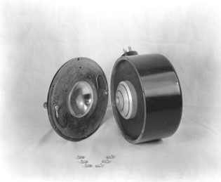
The Ashcraft Lamphouses
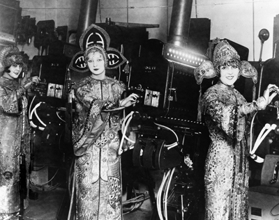
Grauman's Chinese Theatre, Hollywood, California. Projection Room, 1927. Publicity photograph. From the Library of Congress Photographs and Prints Department, LC-USZ62-120536. This charming photo of the elaborately costumed usherettes have them adjusting the controls on the three Ashcraft "600" High Intensity lamphouses. Note the Brenkert Effects Projector up high in the left background.
Although the Ashcraft lamphouse was a very popular carbon arc unit, not much is known about the company or the type of lamphouse initially installed at the Chinese. The lamphouses are called the "600" High Intensity lamps, which seem to have been designed to be used with the "wide film" rumored to be in development.
"High Intensity" arc lamps at this point in time were somewhat specialized, with the Ashcraft "600" able to use 16mm diameter carbons at from 120 to 200 amps, which created an especially hot, white arc.
An elaborate carriage holding the positive carbon both rotated it during the burning, and slowly moved it forward as it burned away — key elements to the formation of the perfect "crater" in the end of the carbon, resulting in the whitest and brightest light.
These are called "condenser arc" lamps in that the flame is close to the front, pointing its light into condenser lenses — the parabolic mirrors used at the rear to focus light into the condensers were around at this time, but were reserved for smaller units. Large reflector units had to wait for the 1950s craze for the drive-in.
These lamphouses were made of very heavy black enameled sheet metal, with doors opening on either side, with nickel trim and handles. They are 28 inches from front to back, 23 inches wide and 24 inches tall, and utilize a 6-inch wide exhaust chimney.
The Ashcraft Manufacturing Company was originally Los Angeles based, but moved to Long Island City, New York.
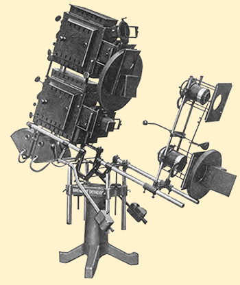
Brenkert F3 Combination Effects Projector
Introduced in 1925 or so, this formidable rig became the standard for effects projectors during the remainder of the 20s — it seems as though almost any theatre worth its salt had one, with many projection technicians of today having stories to tell of finding a dust-covered Brenkert someplace; of being able to cautiously fire them up and having them work!
In any theatre, light is the key ingredient, no less so for Sid Grauman, who by all accounts was a master of lighting design. The Brenkert F3 Combination Effects Projector allowed for untold creative uses, from the projection of 3.25 x 4 inch glass slides containing scenery or lettering, to solid colors created by the gel holders way out in front. This unit has two small carbon-arc lamphouses, again running DC current to the arcs. The two light / slide holder / gel holder lines were together called a "stereopticon;" the two units allowed for cross fades between images or colors by means of linked shutters; one open, the other closed, and vice versa.
Brenkert (and others) had developed the use of mechanical effects — revolving mica or glass discs on which was painted images of water, snow, clouds or fire. When installed in the path of the projector, spring-wound or electric motors on rheostats would rotate the large discs before the lens, thereby creating moving effects. A given effect would be housed in a canister, which could be mounted in any of four ways, so that the effect would descend, or rise or go from left to right or right to left.
ABOVE: Brenkert F3 Combination Effects Projector. Introduced in 1925. From Brenkert Projectors and Effective Lighting-Devices, (Catalogue No. 24), 1925, page 3. Brenkert Light Projection Company, Detroit, Michigan. Courtesy of Thomas J. Mathiesen.
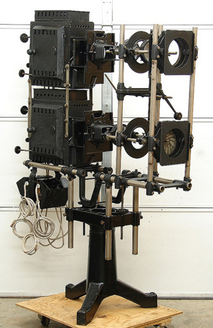
RIGHT: Brenkert F3 Combination Effects Projector. Introduced in 1925, on (probably and F2 base). Photograph by Tom Wilson, via flickr. Unit 72" in height, 84" in width, and 20" depth. This older base doesn't allow for tilting, which the F3 does.
The Brenkert also contained two sets of lenses — one for projecting on your screen, and another for projecting across your stage opening — simply swing the lens you wanted to use into the light path.
The unit swivels on its base, and is designed to tilt easily, allowing it to be used as a follow spot. At the time the Chinese opened, a typical F3 setup would have cost around $750.
The Brenkert Light Projection Company (BLCP) of Detroit, Michigan, was founded by Joseph William Brenkert (1867-1939) in 1907. Originally selling stereopticons and film projectors for Sears Roebuck of Chicago, Brenkert had developed his own stereopticon, focusing on (get it?) selling them to fraternal lodges, and schools. Beginning in 1911, Brenkert relinquished control of the company to his sons, led by Karl (1893-1956) and Joseph, Jr. (1889-1930 / 1932 ?), who developed products, and were joined later by football-playing brother Wayne Brenkert (1898-1979), who, after hanging up his football helmet, joined the sales departement. Brenkert continued to make the model "C" type spot and flood lamp, arc lamp rheostats, the glass slides used in stationary holders, the rotating discs, and these great effects projectors up until 1932. Brenkert expanded into making film projector lamphouses in 1929, then entire streamline moderne projectors in 1939. The company was purchased in 1945 by RCA and then folded in 1954.
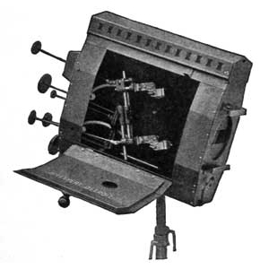
The Brenkert Spot-Flood Lamp Type C3
Next to the Brenkert Effects Projector, there were two follow spots, mounted on a pole close to the port windows, allowing for an operator to stand on its left and swivel the spotlights to "follow" whoever was on stage who needed a spotlight on them. Both of these units were probably made by the Brenkert Company, but the upper one definitely was.
It was the Brenkert Spot-Flood Lamp, Type C3. It had similar arc lamps to be found in the effects projector, though perhaps slightly smaller. It could accept normal-sized gel frames and had a shutter for fade-outs. Another feature was located at the front of the unit and controlled from the rear: a "framing shutter" which would allow the operator to "crop" the beam of light into a horizontal shape in order to illuminate only part of the stage, the orchestra, say. One could go from a "spot" to "flood" by moving the arc lamp closer to the lens. The unit had a holder for colored gels, and it could use a "color wheel."
Brenkert Spot-Flood Lamp, Type C3. From Richardson's Handbook of Projection: The Blue Book of Projection, Fifth Edition, Volume 2, page 945. By F.H. Richardson. Chalmers Publishing Company, New York, 1927. Courtesy of the Internet Archive, scanning and archiving sponsored by Jeff Joseph. Unit 22" in height, 26" in width, and 9" depth.
The Fantom Screen
Program for The Trail of '98 at Grauman's Chinese Theatre, beginning May 7, 1928. This program, from the latter half of the engagement, informs partrons that there will be an intermission between the Prologue and the feature.
One more thing to mention before we leave the Silent Era. In 1927-28, Metro-Goldyn-Mayer had spent a good deal of time, money and effort on a silent picture about the gold rush in the Klondike called The Trail of ’98. M-G-M had big expectations for the film, but to give it a little extra “something” in a marketplace suddenly crowded with “talkers,” for its New York City debut, M-G-M introduced a gimmick they called “Fantom Screen.”
In late 1926, Paramount had released an historical epic called Old Ironsides in a system they called Magnascope, which would show select sequences on a screen greatly enlarged from normal size. These sequences were broken out onto separate reels and shown on a dedicated projector with a shorter focal length lens, while stagehands or electric motors would change the size of the masking. Many theatres around the country adopted the Magnascope approach, including the Chinese itself for the premiere showings of Hell's Angels (which is where Magnascope is explained in greater detail).
For the premiere engagement of The Trail of ’98 at the Astor Theatre in New York City in March of 1928, most of the film was projected in the regular fashion on a large screen which was masked down to a normal size. This screen was hung on a frestanding frame which was outfitted with rollers. During the sequences which were to be enlarged, the footage was located on separate reels and shown on a dedicated projector with a lens which would enlarge the image.
As the screen was rolled by stagehands downstage toward the stage apron,
they would also open the masking until the entire screen was visible. As this was happening, the projectionist would slowly change the focus as the screen moved forward. All of this produced a "floating" effect, and hence the name they gave it: Fantom Screen.
M-G-M had so much confidence in this system that it was suggested that all of their future big-bugeted films would be shown with Fantom Screen, so naturally, when The Trail of ’98 was booked into the Chinese for a run beginning in May, 1928, Fantom Screen was a required part of the presentation.
Grauman typically used the idea and ran with it. His prologue for the film, “Northern Lights” appears to have been a 20-minute parade of vaudeville acts and many extras, including "short skirted damsels," performing before a stage set representing an Alaskan gold rush saloon, called the “Pioneer Dance Hall, Dawson City.”
For the finale, the ensemble of singers and dancers and extras slowed down with the dimming lights, letting their voices fade away. An aurora borealis effect from the Brenkert projector flickered on the dimly lit set, which then began to divide down the middle, slowly sliding into the wings, revealing a normal-sized screen behind the set. Orchestra conductor Will Prior hit the downbeat for the start of the film score, Leo the Lion made his cusomary silent growl, and the credits for the film began
— no intermission.
At the Astor Theatre in New York, Variety’s reviewer mentioned that the film’s two most memorable sequences — that of prospectors climbing the grueling Chilkoot Pass and being wiped out by an avalanche, and another where the main characters negotiated dangerous rapids — were shown with the larger screen in the forward position, while presumedly, the rest of the film was shown on the smaller screen upstage. Grauman’s Chinese probably followed a similar scheme.
When it came time for the screen bandwagon to move forward, the Pioneer Dance Hall set was pulled further into the wings, where it was probably obscured in darkness. When the Fantom Screen returned to its upstage position, the set rolled back out again forming an ingenious framing device for the moving and enlarging screen. All of this required a crew of 30 stagehands!
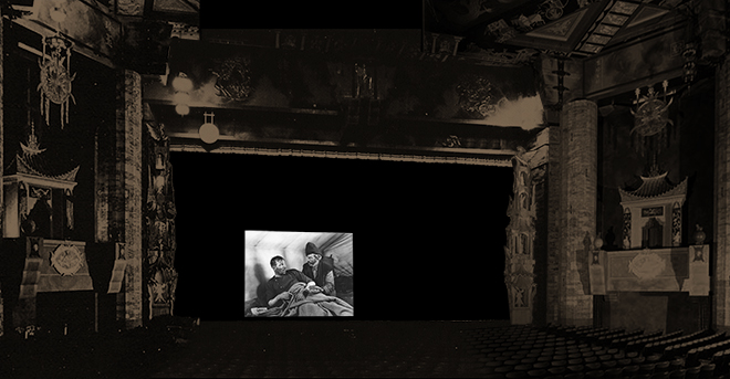
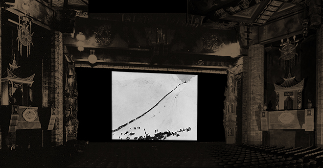
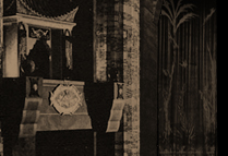
Grauman's Chinese Theatre, Hollywood, California. Auditorium, 1928; photo collage showing TOP: Fantom Screen of 18' x 24' in the rear of the stage, and BELOW: Fantom Screen of 28' x 37" at the stage apron.
The Trail of ’98 is a silent picture, with a musical score written for it by David Mendoza and William Axt. This score was performed by a live orchestra at both the Astor and the Chinese. The performance of the score was recorded at the Astor Theatre, which became the “sound” version of the film, and it is this recording of the music we hear today accompany the film — which was heavily cut, from 127 minutes down to 87 minutes. Only the shorter version remains today.
The Trail of ’98 never became the big hit M-G-M wanted it to be. Although ticket sales at the Chinese were fair (of all the silent films to play the Chinese, The Trail of '98 had the lowest per-performance average), the stagehands at both the Chinese and the Astor began to complain that they were not being paid a fair wage to move the screen up and down the stage. Grauman’s solution: discontinue the Fantom Screen. The Trail of ’98 originally was presented without a break between the Prologue and the feature, but programs printed during the latter weeks of the 7-week run tell patrons of an intermission of 8 minutes, and that the prologue was now called “Yukon Nights." M-G-M never used the Phantom Screen again.
Early Sound Systems: 1928-1933
The Warner Bros. / First National Studio had made considerable commercial success with their Vitaphone sound system, especially with their 1927 film The Jazz Singer. The race to compete for talking picture dollars, which were proving to be very popular with moviegoers, was on. The Vitaphone system synchronized the projector with a recorded disc, while the Movietone system carried the sound on the film itself.
Grauman's Chinese Theatre, committed to providing outstanding attractions to the public, was, in 1927-28, free to book films from any distributor who had a picture of suitable prestige. During the silent era, Mr. Grauman had booked some very big names indeed: DeMille, Fairbanks, Chaplin. But all of that was swept aside in the clamour to obtain talking pictures. Once the equipment was installed, a steady supply of films was needed, so Grauman turned to Metro-Goldwyn-Mayer, who were planning on making sound films regularly with the Movietone system, which they had licensed from the Fox Film Corporation.
Fox Film had acquired the Movietone system patents, but they also had a huge chain of theatres to show their films in. However, by 1928, Fox Film Corporation was struggling; they did not control any large theatre in Los Angeles. Fox was looking for a way to have a major showcase in the Los Angeles market.
Complicating matters during this time, was Grauman's participation in the Chinese Theatre operations. In early 1929, Grauman had sold his interest in the theatre to the newly-formed Fox West Coast Theatres, with the commitment to playing M-G-M pictures already in place. Grauman's buyout stipulated that he would continue as manager, but this seems to have been a rocky relationship, with Grauman's Prologues accompanying the feature film alternating with periods where other stage fare was booked.
So many early Fox Film Movietone films were presented. But before then, Grauman had an agreement with Warner Bros. with their Vitaphone system, to play their superproduction of Noah's Ark for a run at the Chinese in November of 1928, despite the fact that Warner's had opened their own large theatre on Hollywood Boulevard only five months before.
All of this confusion does not allow a strictly chronological approach to what happened when sound came to the Chinese. What is known is that Movietone had to have been installed first for the run of White Shadows in the South Seas in August, 1928, followed by the Vitaphone run of Noah's Ark in November, 1928. Given Grauman's familiarity with the Vitaphone system, and knowing that Movietone was a competing format, it is probable that both systems were installed at the same time. Although it might have been first one, Movietone, then the other, Vitaphone.
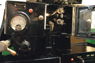
By late 1928, the Powers 6B Improved Cameragraph projectors could have been altered to accommodate an RCA or Western Electric-made sound reader, or sound head, under the projector head, with the Vitaphone turntable installed to the left of the projector's base. Let's take these subjects in order:
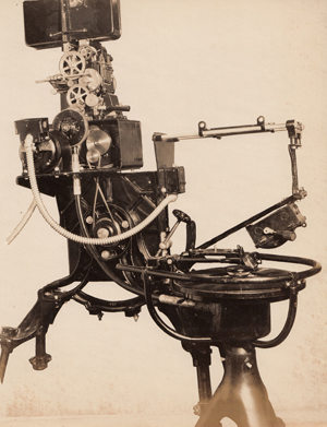
Powers No. 6B Cameragraph Projector with RCA sound on film head and sound on disc attachment. The lamphouse is missing from this photo. Photograph courtesy Tom Wilson via flickr.
The Movietone System
While Thomas Edison and his lab had been experimenting with combining his Phonograph talking machine with his Vitascope movie systems, a man by the name of Theodore Case (1888-1944) became interested in materials which would react to light. If sound waves captured by a microphone could cause a stylus to vibrate over record wax, why not use sound waves to control light? After developing a light-sensetive vacuum tube / signaling device for the Navy in World War I, Case teamed up with Earl I. Sponable (1895-1977) to solve the problem of talking pictures.
However, another man named Lee De Forest (1873-1961) had been working on a sound system he was calling Photofilm. Even after hanging around Berlin with Josef Engl (1893-1942), Hans Vogt (1890-1979), and Joseph Massolle (1889-1957), the developers of the Tri-Ergon process, De Forest was still producing poor-quality recordings. So in 1922, the Case / Sponable group began sharing their technology with De Forest.
There were hurdles to overcome, however. De Forest had been subjecting a regular light bulb to the sound coming from the microphones, but the filaments couldn't take it, and burned out immediately. Case developed the "aeo-light," which is a gas-discharge glow lamp (a neon tube is a gas-discharge lamp filled with neon gas) whose intensity can be varied by changing the voltage fed to it. Feed impulses from a microphone into it, the "aeo-light" flickers accordingly.
The flickering light would be photographed through a slit on a thin strip on the left side of the image in the camera. This came to be called the "soundtrack."
The cell receiving light shone through the soundtrack during playback is a Case invention also. It is called a thallofide cell, which utilizes thallium sulfide (thallium previously being used as a rat poison). This cell's electrical conductivity could change according to how much light it received, creating an audio signal.
Using this newly-formed system, De Forest produced a number of short films of vaudeville acts, ostensibly as test films. When De Forest took these films on the road in 1925, Case claimed patent infringement, and a war of words erupted between the Case camp and the De Forest camp regarding who was trying to cash in on who's work.
Apparently, Case took the whole mess to William Fox, head of Fox Film Corporation. At that time, Fox was overextended: he was trying to buy stock in M-G-M; the studio was producing a great number of films while building and operating a huge chain of theatres across the country. A lock on sound films might be the answer. Beginning in 1926, Fox bought all the patents from all the groups trying to record sound on film: the Case / Sponable group, the Tri-Ergon German patents, and several others, forming the Fox / Case Corporation. They called their new effort "Movietone."
To make Movietone happen, Sponable (who later, as Chief Research Engineer at 20th Century-Fox, helped bring both CinemaScope and CinemaScope 55 to fruition) worked on the mechanics of producing a camera, first with Bell and Howell, then with the Wall Camera Company, while Case seems to have concentrated on making sound reading "heads" for the projectors. Movietone was first shown to the public in New York City in early 1927. Movietone adopted Vitaphone's approach of placing the speakers behind the picture sheet itself, which was punctured with a pattern of tiny holes to allow the sound to come through. This technique carries on in every movie theatre on Earth right down to the present day.
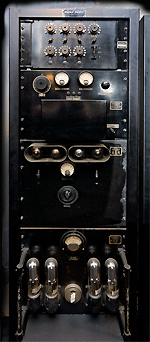
The Western Electric Universal Base
This is where Western Electric enters the picture.
Western Electric, a division of Bell Telephone, knew what was in the wind. Prior to the talkie era, Western Electric had been dabbling with the first public address systems, and they had developed the technology which would eventually appear as the Vitaphone system. So Western Electric became the "go-to" outfit to make and market many of the pieces of the talkie puzzle.
Western Electric was so aware of what was going on, that they developed a product called the "Universal Base" which was a projector base containing a Vitaphone turntable, a sound head for reading sound-on-film, and a take-up reel. All you had to do was park your old projector on top of it. The Western Electric Universal Base's sound head could read all three of the competing sound-on-film formats: Movietone's variable density soundtrack, RCA's Photophone variable area soundtrack, where the sound waves were scribbled down as a wave form by a very quickly-moving mirror, and Western Electric's system, which converted sound waves into horizontal bars, giving Western Electric sound a distinct advantage, as the image of the soundtrack was much easier to develop and duplicate in the film lab, allowing for more complex sound editing and mixing.
Western Electric Universal Base with turntable, 1928. Shown with British-made Kalee projector head, upper magazine and lamphouse. Photograph courtesy of The Phoenix Cinema, East Finchley, London, England.
It is is probable at this point that the Chinese installed the Western Electric Universal Base with Turntable, then placed their Powers Projectors on top. But then again, it was possible to purchase the sound head and turntable separately, as shown in the above photo.
Since the first sound-on-film engagement at the Chinese was three months ahead of the first Vitaphone engagement, Grauman probably got both systems at once by installing the Western Electric Universal Base. Grauman had played the first Vitaphone feature, Don Juan at his Egyptian Theatre, so he probably understood that equipping the Chinese with the Vitaphone system would be wise.
Kevin Wheelan Screening Room, Hinchley Wood, Surrey, England, United Kindom. Projection Room, 2009. LEFT: Western Electric Universal Base with Kalee 12 Projector from 1940, and Monarc Lamphouse from 1939; ABOVE: Western Electric Universal Base. Western Electric Soundhead; BELOW: Western Electric Universal Base. Vitaphone Turntable. Photographs by Kevin Wheelan. Via Film-Tech.com
The Vitaphone System
We also have Western Electric to thank for the Vitaphone. The adoption of this sound-on-disc system by Warner Bros. in 1925 led to the release of The Jazz Singer in 1927, and the rush to talking pictures. The telling of the Vitaphone story is a much easier and linear story to tell, because of the fact that one company, Western Electric, developed the system, and only one studio used it.
The Vitaphone system was the result of a number of devices all coming into play one after the other in what seems like a logical progression toward a talking movie. First, Western Electric purchased the rights to Lee De Forest's Audion Amplifier Tube in 1913. This amplifier made it possible to work out a public address system, when combined with the Condenser Microphone of 1916, designed by Edward C. Wente (1889-1972), and which was redesigned in 1922.
Although Western Electric was developing their own sound-on-film optical sound, they were attempting to do the same thing with recording discs, which had greater fidelity than what was possible with optical sound at the time. Unlike Edison's Phonograph, where sound waves were replicated in peaks and valleys read by a needle forced into the grooves by gravity, the Vitaphone sound waves oscillated sideways, with the groove retaining a constant depth.
Because of this feature, the "bandwidth" of these records was considerably better than Edison's, due to the fact that there was room for more detail in the grooves. While it was possible to achieve
greater fidelity by spacing the grooves further apart, cramming too many grooves into too small a space impacted performance, and so, 92 grooves per inch became the standard.
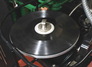
As originally developed, the Vitaphone system consisted of a projector and a 16-inch turntable. Both were interlocked with each other, the film running at 24 frames per second, and the turntable turning the disc at 33 1/3 revolutions per minute. The 16-inch Vitaphone record could hold 11 minutes of mono sound, so each 1,000 foot reel of film had its own one-sided disc.
The projectionist would place a "start" frame in the gate of the projector, then, after placing the correct disc on the turntable and locking it down, would turn the disc until an arrow imprinted on the label of the disc was at 6 o'clock from the operator. Then, one would place the pickup right there on the first groove closest to the arrow. The groove wound around from the inside to the outside. Then, since these two start cues had been lined up, the projector would start, and theoretically the sound and the picture would be in sync.
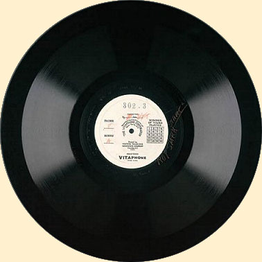
Vitaphone Disc for short film Pastimes, Warner Bros. / First National, 1926. Camden New Jersey, Victor Talking Machine Company. 16 inches diameter. From the Library of Congress, Motion Picture, Broadcasting and Recorded Sound Division, Unknown Number. Oddly enough, most of these labels contain no information as to picture name or reel number.
Vitaphone records were made of the same material conventional 78 RPM records were made of: shellac compound with a coating of finely pulverized slate dust. This surface was meant to wear down the needle to conform to the groove profile on the disc. The stylus for the pickup was heavy, and so the steel needle would begin to wear out the grooves beginning with the very first playing. A grid full of numbers on the label was where one was supposed to check off how many times the disc had been played. After 20 plays, one was supposed to toss it out and go to the "backup" record.
But anyone familiar with either film or records knows that:
A. Films break, causing footage to be lost
B. Records skip
Supposedly, a proper Vitaphone set-up had controllers which could advance or retard the film, allowing a projectionist to attempt to correct sync if things got out of hand, but as can be imagined, this meant that operators had to keep constant watch over synchronization. Boring.
When the film broke, it would be out of sync with the record, so each Vitaphone picture print carried footage numbers along the edges. Each foot of film got a number, beginning with one, and so, a projectionist would be able to examine the print, determine how much footage and frames were missing, and cut some black leader into the hole, making everthing in sync again.
If the disc skipped, one was faced with one of two options: Stop the show and refund everyone's money OR, go to the backup disc and start over with the last reel shown.
Simpler times.
The First Loudspeaker System Installation
Now that we have sound signals coming from the projector, what next? Amplification and sending it along to a loudspeaker. Only the developments in the design and implementation of the first pubic address systems made the "talkies" possible.
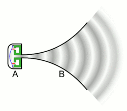
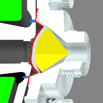
Everybody knows that when you speak through the small end of a cone, it gets louder on the other end. The early designers of speaker systems tried to solve the problem of how to place some sort of transducer (which would receive audio signals and convert it into a motion of some kind) in the unit at the small end of a cone, which would help make the sound louder. As early as 1915, Edwin Jensen (1886-1961) and Peter Pridham of Magnavox created the first practical moving coil loudspeaker, but the design still in use today was patented in 1924 by Chester W. Rice (1888-1951) and Edward W. Kellogg (1882-1960). Kellogg also worked on RCA's Photophone sound recording system.
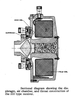
What happens in a moving-coil driver is this: you have a donut-shaped magnet, the field-coil, surrounded by a wire wrapped around a tube surrounding the field coil. It is called the voice coil. Under the hole in the donut is a cone-shaped diaphram, which is held in such a way that it can move in a line toward the two magnets or away from it.
Cross section diagram of Western Electric WE 555 loudspeaker driver.
So the field coil is always magnetized, while the current passing through the voice coil fluctuates (according to the impulses coming from the soundtrack or record). The resulting magnetic forces cause the diaphragm to oscillate in and out, thereby pushing the air before it, recreating a close approximation of the original sound waves. Attach that to a horn-shaped device to handle the differences in acoustical impedance, and there you have it: a loudspeaker.
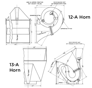
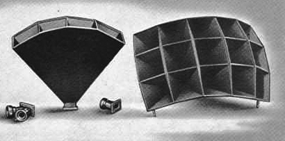
Back over to Western Electric, who needed proper speakers if they were to make their Vitaphone system work. Under Edward C. Wente (1889-1972), Albert. L. Thuras (1888-1945) and Stanley Watkins (1888-1975), working to meet the premiere date of August 6, 1926 for Don Juan, developed a driver where the field coil was a very strong electromagnet powered by secondary rechargable lead / acid batteries and connected to a "exponential" horn 12 feet long, curled on itself, like a snail, to conserve space. The horn expands exponentially along its length, giving it a very smooth response. This design could produce louder sounds with less distortion — perfect for the talkies. They called the driver a "receiver;" the WE 555. And since two heads are better than one, two different speakers were developed to use in tandem: the 12-A, hung high above the stage behind the screen, and the 13-A, which typically sat in the orchestra pit pointing up towards the auditorium ceiling.
Plans for Western electric 12-A and 13-A speakers. Courtesy of www.itishifi.com.
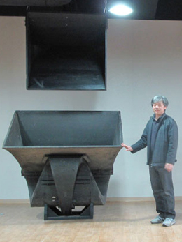
Dr. Steven Bae with Western Electric 12-A and 13-A speakers at the Silbatone factory, Seoul, Korea. Courtesy www.silbatoneacoustics.com
Western Electric 8-B Speech Input Preamplifier unit on top over the 9-A Power Amplifier. Introduced in 1927. Photo courtesy kjq.us.com.
The horns were made completely out of hardwood, with each segment of the curve hand-cut and glued together. If straightened out, the 12-A was 11 feet long, while the 13-A was more like 14 feet long. They were about 200 lbs. each, with the mouth of the 12-A horn being 45 inches square. The 13-A horn at the mouth measures 43.5 x 62 inches. The range of frequencies they were capable of reproducing was from 63 to 5000 hertz (Hz).
The idea of having two different speakers arranged like this is interesting: at the beginning of Vitaphone, Warner Bros. produced two types of "programs." One type was mostly short films of vaudeville or musical acts. The early Vitaphone feature films were mostly silent films with a recorded orchestra playing along.
The idea was this: for films with mostly dialog, the 12-A speaker behind the screen would be used. In films with only orchestral score, the 13-A with its greater output potential would be used, since it was usually placed right in the orchestra pit — so that the recorded orchestra sound would come from a logical place.
After all of this was set up by the Western Electric people, the projection operator would choose via L pad knobs which setting to use: "A" for vaudeville shorts and talkies with dialog (the 12-A), "B" for orchestral scores (the 13-A), and the "C" setting for films with equal amounts of dialog and orchestra (both 12-A and 13-A speakers). The A, B, or C horn selection is indicated on the label of the record. In our sample above, it is just to the lower left of the center spindle.
Western Electric amplifiers at this time usually consisted of two parts; the 8-B which was the preamp, and the 9-A, which was the power amp. Since there were three 12-A horns behind the screen, and since more than 3 watts would blow out a given 555 Receiver, the 9-A power amp (soon to be replaced by the 10-A), did not have to have huge output capacity. The 9-A amp is rated at 1.69 watts output.
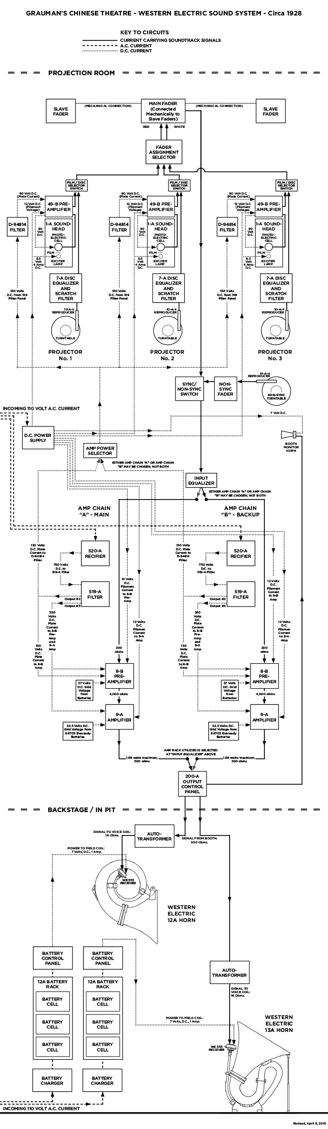
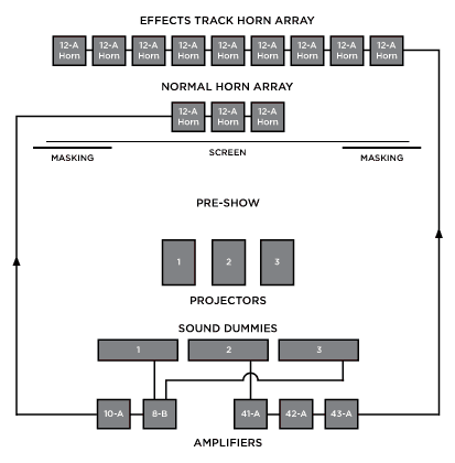
How It All Works Together
Western Electric manufactured a staggering array of components which could all be used in various combinations, depending on the individual theatre. It was because of this welter of gear / system design options that Western Electric insisted on an engineer / installer come out from New York in order to design and supervise each theatre installation.
What we have here is a simple block diagram of what was probably installed at the Chinese in August of 1928. There are three sections to this diagram: the top is the front part of the booth — the projectors. The middle section is the rear wall of the booth — the amplifier racks. The bottom section is all the gear on the stage — horns and their support components.
A very special thanks are due to theatre historian and theatrical electrician Mr. Bill Counter, as well as to the technical advisor to The Vitaphone Project, Mr. Steve Levy. Additional research has been provided by Mr. Peter Lankshear. We have all scratched our heads over this one, folks!
To enlarge this diagram in a new window, click here. To view as a PDF in a new window, click here.
Grauman's Chinese Theatre, Hollywood, California. Western Electric Sound System diagram, circa 1929. Diagram by Kurt Wahlner.
Because these early films were shown on 1,000 foot reels, making for only 10 minutes of screen time, working in a booth during this period was hectic and labor-intensive. In order to handle all of this, there was typically one operator per machine (figuring that all three projectors ran reels in succession, in order to give all three projectors the same amount of running hours). There might have been a sound man who would attend to all of the sound gear to keep it all happy. Finally, there was a young apprentice who would run the rewinder, put the rewound reels back in their proper slot in the rewind bench, hand the correct reels to the operators, and so on.
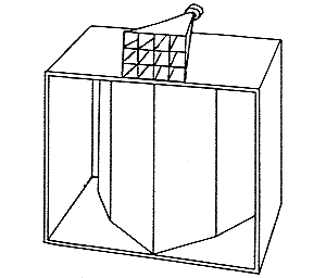
The Speaker Trolley
In order to move the speakers in and out of position behind the screen quickly, an ingenious system was created. The design challenge was to move these large, thick speakers out from behind the screen without taking up valuable space in the stagehouse. Space which was needed for scenery. The speaker or speakers were placed in a large wooden box, which was called an enclosure. The enclosure was then suspended by cables, which went up to a trolley on a track attached to the underside of the theatre's grid near the top of the stagehouse. The trolley track went off stage left (opposite the switchboard on the right), where the enclosure could rest without being in anyone's way during the stage presentation. The enclosure was probably dragged back and forth manually by the stagehands.
ABOVE: Grauman's Chinese Theatre, Hollywood, California. Theoretical operation of speaker trolley, circa 1929. Drawing by Kurt Wahlner. LEFT: Hollywood Panatages Theatre, Hollywood California. Stage with speaker enclosure, circa 1930. Photograph by J. Howard Mott (1888-1937). From the Mott-Merge Collection, California State Library, Sacremento, California. These four speakers are probably Western Electric's 15-A horns, which were made of lighter plywood than the hardwoods used in the 12-A and 13-A horns. This system may have been copied from the system to move speakers backstage at Grauman's Chinese Theatre, which, by the time the Hollywood Pantages opened in 1930, was also in the Fox West Coast Theatres chain.
A Startling Discovery
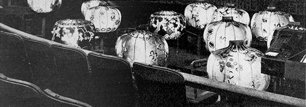
A story has long been told about what happened when the talkies came to the Chinese. It has to do with the two large bronze pylons on either side of the stage, as well as the Chinese-lantern music stands in the orchestra pit.
The pylons were bedecked with shimmering shards of crystal pendants, and when the sound came out of the horns, it caused them to tinkle unmercifully. Both pylons were removed.
After the pylons were gone, the rattling continued, and it was discovered to be coming from the Chinese paper lantern music stands. The stands were slightly built, since they were supposed to look like paper lanterns, outfitted with red / green / blue light bulbs to illuminate the outside, and white light bulbs for the musicians to read their music by. But they rattled also, and so, were replaced with the more conventional gold-fillagree music stands seen in other theatres around the country.
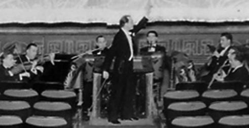
Grauman's Chinese Theatre, Hollywood, California. Orchestra Pit, circa 1931. Publicity Photograph. Oscar Baum shown conducting the Grauman's Chinese Symphony Orchestra during an unknown performance, showing the conventional music stands which replaced the original Chinese paper lantern music stands.
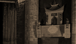
Grauman's Chinese Theatre, Hollywood, California. Orchestra Pit, 1927. From Grauman's Chinese Theatre: A Console Feature, by Terry Helgesen; Console Publications, Pasadena, Caifornia, no date, circa 1968. This unfortunately cropped picture shows the original Chinese paper lantern music stands in the pit.
The 1930 engagement of Hell's Angels represents the first time the Chinese Theatre booth was grunged out to accommodate a film. It would not be the last time, either.
Howard Hughes (1905-1976) produced this drama of fighter pilots during World War I, and was rumored to have been the most expensive film made up to its time — the headstrong Hughes was determined to make it a hit — his film had to "WOW" the public. An elaborate presentation scheme was devised, consisting of several components; projection, sound, and screen.
The first thing that had to go were those old Powers Projectors. Many advancements had been made in projector design, and the Powers brand, owned (since 1925) by the International Projector Corporation (owners of the Simplex brand), did not allow the Powers brand to keep up.
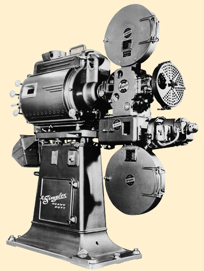
So Simplex projectors were installed at the Chinese. Not just Simplex projectors — Super Simplex projectors.
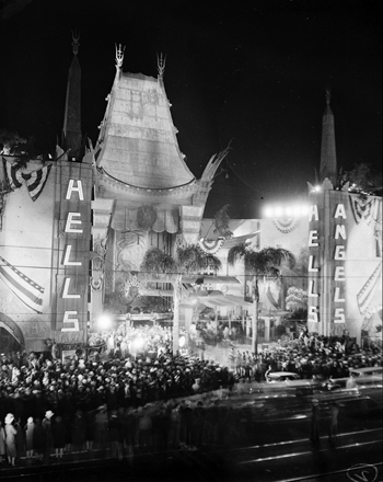
Grauman's Chinese Theatre, Hollywood, California. Exterior, May 27, 1930. Hell's Angels premiere.
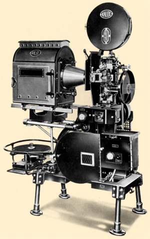
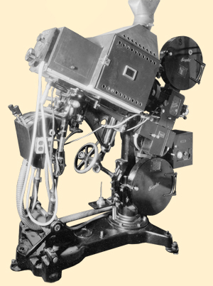
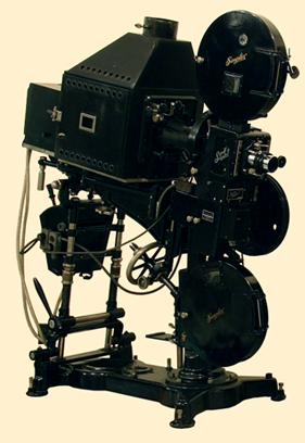
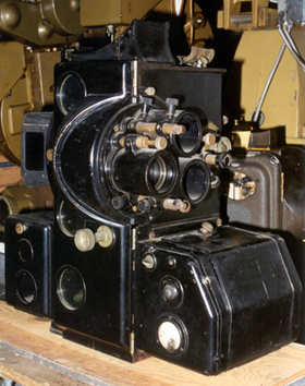
The Super Simplex Projector
Peabody Opera House, St. Louis, Missouri. Projection Room. circa 1930. Super Simplex projectors with Hall & Connolly type HC-10 lamphouses, Western Electric 206 soundheads on Simplex Model M pedestal. Photo courtesy Tom Wilson via Flickr.
The Simplex projector had been around almost since the beginning of projected films. The story begins with the first presentation of projected films at Koster and Bial's Music Hall in New York City on April 23, 1896. The projection machine that evening was operated by a man named Edwin S. Porter (1870-1941), usually known to film buffs as the man who directed The Great Train Robbery for Edison in 1903.
Edwin Stanton Porter (1870-1941). Date unknown.
A Pennsylvanian, Porter worked various odd jobs as a youth, but leaned toward electrical devices in his early teens. In 1883, he joined the U.S. Navy, where he distinguished himself by improving electric devices and communication systems. After running the show at Koster and Bial's in 1896, he traveled the world, barnstorming films at fairs and circuses.
In 1898, he found work at the Eden Musée, which was an amusement hall / wax museum in New York City. A number of Edison productions were using the place as production headquarters, so Porter began assisting in the productions, as well as being the impresario of the film programs at the Musée.
The next decade was a heady one for Porter. Having started in projection and presentation, he had a keenly developed sense of what audiences of the time would accept, and so he rose to become the most creative of the filmmakers at Edison, culminating in his 12-minute epic The Great Train Robbery (1903).
He also had time to start a projector company. Starting in 1908, Porter and two projectionists / engineers from the Eden Musée, Francis B. Cannock and Mike Berkowitz, began designing what was to become the Simplex in a back room of O'Keefe's Saloon at 42nd and Vanderbilt in NYC.
The Simplex projector introduced in 1909 - 1910 was an immediate hit, selling thousands upon thousands each year all over the world. Part of its popularity revolves around its practical features, which were constantly added to and refined all through the silent period. Features which were not available (if ever) on other projectors, such as an intermittent unit which could be easily changed out if needed, changeable aperture plates, a framing device (allowing the picture to be framed properly if threaded incorrectly), variable speed controls, just to name a few.
After International Projector Corporation (IPC) was formed in 1925, Simplex became the premium brand, easily making the transition to the early sound era. When the Super Simplex was introduced in 1930, earlier machines were known as "Standard's." The improvements made to the Super Simplex were legion:
Super Simplex projector head. Front view. 1930. From the Journal of the Society of Motion Picture Engineers, November, 1930, page 644. "Some New Projection Equipment" by Herbert Green (International Projector Coproration). Courtesy of the Internet Archive.
Rear shutter. By enclosing the whirling shutter and moving it between the light source and the gate, the projector became a safer machine. This move kept the film somewhat cooler also — another critical feature for running Magnascope.
A larger lens barrel of 2 25/32". This remained standard until the 50s.
The lens could easily shift its center from silent to sound apertures via a lever on top of lens mount — an important consideration for running Hell's Angels.
Slide-in changeable aperture plate. This made it very easy to switch from silent aperture to sound aperture to Academy mask.
Larger case for more working room while threading.
Double bearings on the intermittent sprocket for a steadier picture.
New framing knob arrangement sticking out on operating side. Previously a lever in back.
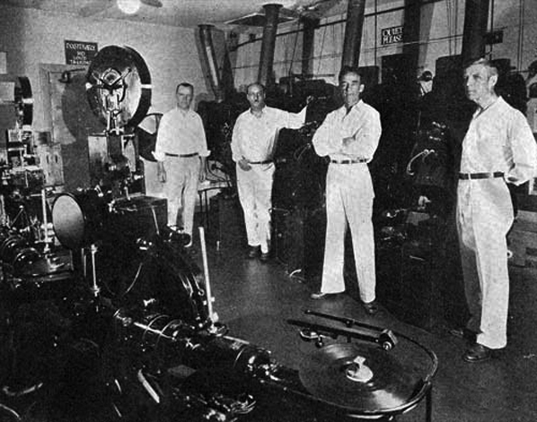
It is possible to state that three Super Simplexes replaced the three Powers projectors by the May 27, 1930 premiere of Hell's Angels, due to an eyewitness description of the booth as it was in 1930. Technician Frank Richardson, whose Richardson's Handbook of Projection had gone through five editions by 1927, wrote a regular column for the Exhibitors World Herald called "F. H. Richardson on Projection." In the November 8, 1930 issue, there is a column entitled, "The Capital City of Filmdom."
In it, Richardson states that he is visiting Los Angeles in time to visit the summertime convention of the International Alliance of Theatrical and Stage Employees (I.A.T.S.E.) Convention, presided over by its president, a Mr. Earl Hamilton (chief projectionist at the Metropolitan Theatre, in Downtown Los Angeles). He goes on to describe a visit to the Chinese booth, headed by Chief Projectionist, Mr. Fred E. Weaver, inventor of the Weaver Dowser. We quote:
The projection room is rather crowded with equipment. It has three Super Simplex projectors equipped with the new Ashcraft "600" super-high intensity lamps. The lamphouse almost hides the projector. The sound is handled by Western Electric equipment. The sound is on a separate film, which is run on a "dummy." The consensus of the Chinese theatre projection staff and those projectionists of other theatres in which this method is used, is that it is a decided improvment on the method in which both the sound and the picture are reproduced from the one film, which opinion I endorse.
The projection staff of the Chinese consists of F(red) E. Weaver, chief, R. D. Babcock, Dave Koskoff, Al Lick and Art Schroeder.
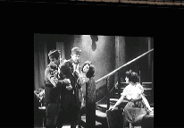
Grauman's Chinese Theatre, Hollywood, California. Projection Room, 1930, photograph taken during the run of Hell's Angeles. Projection staff, including Head Projectionist Fred E. Weaver (probably the man with arms crossed), Super Simplex projectors behind them, and sound reproducers in foreground. Photo courtesy of Moviemice.com.
I might add, as a bit of interesting information, that the projectors are equipped with a small blower fan from which the air is conveyed through a flexible metal pipe ending at the top of the cooling plate, where the air passes down over the aperture. In the opinion of Chief Projectionist Weaver, this has the effect of removing fully 75 per cent of the heat. The installation is very simple, not at all costly and is highly effective. Some of you old department fans may remember that this particular thing was recommended by me many times in past years. Equipment manufacturers, however, did not adopt the suggestion, and as a result they have suffered great inconvenience from the warping of projector frames and parts, and the industry has sustained huge losses in film, to say nothing of the box-office losses caused by injury to the shows as a result of buckled film, all of which might easily have been averted had my suggestions been heeded years ago.
If only they had listened to F. H. Richardson!
Super Simplex projectors with Hall & Connolly type HC-10 lamphouses, Western Electric 206 soundheads on Simplex Model M pedestal. From the Collection of Tom Wilson. Via Flickr.
Richardson's description of the running of Hell's Angels with the picture and the track separate — "double system" — tallies with other descriptions of how the film was presented in New York and London engagements. But why was this done?
As Richardson mentions, running the sound on a separate machine reduces heat warping on the film as well as reducing the mechanical motion the film is subject to — resulting in a better reading of the information on the optical track.
35mm silent aperture release print on the left, compared with the same scene contact printed into the Academy Mask format with Western Electric soundtrack. Of course, awkward cropping of the frame could be avoided if one composed for the Academy Mask while shooting.
But there was another reason for this method. Hughes had begun to make Hell's Angels as a silent film in 1927. With the popularity of talkies, Hughes felt the need to add sound to his film. James M. Thorburn was hired away from Western Electric to supervise adding sound to Hughes' epic. But there was a small difficulty; some of the picture (the expensive parts) had been shot in the silent aperture, while shooting sound was usually being done at the recently instituted "Academy Mask" which cropped the top, bottom and side of the silent frame.
Since Hughes wanted to show the air battle sequences in his film in Magnascope (see below), which would require the best possible image quality, it was decided to shoot all the new sound scenes at the silent aperture as well, and carry the soundtrack separately.
So, after the three Simplex Supers were installed, the three Western Electric Universal Bases were relocated to run in a line near the backwall of the booth. Then, they were outfitted with three of the older Simplex Standard projector heads and feed reel magazines. The intermittents of the Simplex Standards had been removed to reduce "flutter," while the Universal Bases were modified to accommodate the extra selsyn motors required to keep everything in synch. This accounts for the lengthening of the distance between the heads and the turntables (this was done so that in case a Vitaphone release was booked, the format was all ready to go).
ABOVE: Grauman's Chinese Theatre, Hollywood, California. Projection Room, 1930. Photgraph taken during the run of Hell's Angels, showing Western Electric sound rack on the left, and two of the three sound "dummies" used to run the separate soundtrack for the film. Photo courtesy of Moviemice.com. RIGHT: Western Electric Universal Base outfitted with Simplex Standard projector head and feed magazine. The "dummies" at the Chinese would not have the shutters in the front. Photo courtesy of Moviemice.com.
Western Electric Amp rack with 41A, 42A and 43A amps. Courtesy www.silbatoneacoustics.com The knob high on the left side with the copperish scuffing is the main volume control. We imagine that this thing glowed quite nicely in the darkened recesses of the Chinese Theatre booth.
Sound from any of the three "dummies" as they were called, would get fed into the regular theatre sound amplification system, consisting of the Western Electric 8-B preamp, and the newer 10-A power amp (replacing the 9-A amp after 1928 or so), capable of delivering as much as 19 watts to the three 12-A horns behind the screen. But they probably produced more like 9 watts during the loudest passages, which the three-horn array could easily handle.
But there was more.
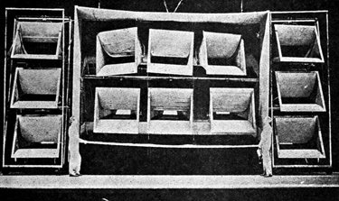
Hughes felt that the sounds coming from the three 12-A horns at the Chinese didn't capture the deafening sounds of airplane engines, machine guns, crash landings and explosions he had in mind for Hell's Angels. So for this engagement, the Magnascoped sequences would be augmented with a second optical track containing these sound effects. This is considered the very first film ever to be presented in a multi-channel format in any theatre.
The only way to get the desired volume with the 12-A horns without horrible distortion was to increase their number. Sounds coming from the extra sound effects track were sent through a separate amplification system entirely, consisting of the new Western Electric 41-A, 42-A, 43-A combination, which was fed to nine (that's right, nine) extra 12-A horns, arranged around the regular three horns. 30 watts was as much as the 43-A amp could produce, which was a good fit, since the nine-horn array had a combined total power rating of 27 watts.
The center projector (number 2) was used for the Magnascope sequences, for reasons which will be explained below. It was only these sequences which utilized the additional sound effects track, which was read off of the center sound dummy (number 2). Because of the need to make changeovers to the regular set-up, a special switching device had to be created to allow the regular track to be read off of either sound dummy 1 or 3 in combination with sound dummy number 2 running the extra effects track for the Magnascope sequences.
A complex series of events occured in the booth for each showing of Hell's Angels (see animated schematic below), all of which had to be performed according to a schedule hung up in the booth someplace. One little slip, and disaster!
The Chinese Theatre's speaker trolley cabinet was augmented with three more horns, and the other six were rolled into position on two towers of three horns each flanking the speaker trolley cabinet. All of the cables for the whole system were probably routed down to the speaker trolly cabinet, and when it was in position, stagehands would connect the horns in the towers. This was done so that the whole speaker array could be flown up and wheeled out of the way during the Sid Grauman Prologue which accompanied each showing of the film.
Grauman's Chinese Theatre, Hollywood, California. Stage speaker array for the film Hell's Angels, 1930. From The Journal of the SMPE, "Progress Report" December, 1930, Volume XV, number 6, page 777. Courtesy of Dan Sherlock.
In the same issue of the SMPE Journal containing the photo of the 12 12-A Horn array, there is a description of how sequences in Hell's Angelswere projected in Magnascope. Developed in the mid 1920s by Glen Allvine and Lorenzo Del Riccio while working for the Famous Players-Lasky division of Paramount, Magnascope's scheme employed special sequences isolated on reels on their own, which would then be projected through a shorter focal length lens onto a screen much larger than what was normal during the silent era. Black masking would move either by motor or manually by stagehands after a changeover, resulting in a very impressive change of scale.
Normally at the Chinese during this period, the screen was 18 feet high by 24 feet wide for the 1:1.33 picture. Magnascope made allowances for the aspect ratio of the enlarged screen, suggesting that a wider image might be just the thing for these "special" sequences, but also due to the fact that stage openings did not usually remain squarish as they got bigger, but more horizontal — as was the case at the Chinese.
The SMPE Journal states that the Magnascope screen was 24 feet tall by 37 feet wide, resulting in an aspect ratio of 1:1.54. Although Magnascope was developed by Paramount, who first used it for a 1926 film called Old Ironsides, the practice of showing a film in this manner spread throughout the studios and theatre chains until it got to the point that almost every first-class theatre had the equipment. Hell's Angels did not advertise that the film was showing in Magnascope, which probably made the impact of the flying scenes all the more spectacular to audiences.
Grauman's Chinese Theatre, Hollywood, California. Presentation scheme diagram for Hell's Angels, from May 17, 1930. Diagram by Kurt Wahlner.
Hell's Angels was shown in two parts, with an intermission. The first hour-long half sets up the story during its first and second reels of 2,000 feet each, then Magnascope takes to the air during a 20 minute long (a full 2,000 foot reel) sequence of a Zeppelin attempting to bomb London during World War I. After the break, there is another full 2,000 reel (20 minutes) of set-up, followed by a very full reel of Magnascope (23 minutes) showing Our Heroes flying a stolen German bomber in a daring attempt to blow up an enemy ammo dump. They are captured and the final reel (another 20 minutes) shows what happens to them in captivity.
So the film is cleverly structured to take advantage of Magnascope, and since there wasn't enough equipment to changeover from one "triple" system reel (one picture, two sound tracks) to another, which would have required four sound dummies, for once Mr. Hughes seems to have abided by a technical limitation dictated by his overall presentation scheme.
The projector in the center seems like the obvious choice to play the Magnascope reels, since horizontal keystoning would be eliminated for the uncommonly large screen. While projectors 1 and 3 were using 3.25 inch lenses for the regular size screen, the center projector would have a 2.25 inch lens and special aperture plates for cropping the silent aperture down to the 1:1.54 shape. The tilt of the projector itself would have to change also, since the picture grew taller, rather than expanding on all 4 sides.
The projector assigned to show the Magnascope reels also had to produce more light to illuminate the larger screen. Two methods were employed to accomplish this: increase the exposure time of the film in the gate, and increase the amperage going to the carbon arc lamphouse.
In order to increase the exposure time, the center projector had to be mechanically altered: Simplex had developed a "high-speed" intermittent, which would pull the film down faster than normal. This noisier intermittent pulls the film into the gate with a much quicker action and holds it there longer.
The high-speed intermittents became popular later in drive-in theatres, which required more light for their large screens. But operators from that time and later complained that this intermittent broke badly-made cement splices and later, the badly-made tape splices as well. With this in mind, it is easy to imagine the violence with which the high-speed intermittent subjected film to.
The print of the Magnascope sequences had to be as perfect as possible to avoid breaks.
The high-speed intermittent worked in conjunction with a new shutter. Normally, the Super Simplex shutter blades (the solid part) were 90 degrees each. However, the Super Simplex shutter was adjustable. For Magnascope, it was recommended to be reduced to only 72 degrees, allowing light to come through for a longer period. Since the high-speed intermittent yanked new frames into position faster, this combo worked perfectly. Using the high-speed intermittent without adjusting the shutter to 72 degrees would not get you a brighter picture. Reducing the shutter to 72 degrees without the high-speed intermittent, and you would get "travel ghost." Both pieces of the puzzle were needed.
Typical projector 90 degree shutter diagram, showing normal "double" exposure of each frame.
The combination of the high-speed intermittent pulling the frames into position faster and the 72 degree shutter, allows for a longer exposure time for each frame, resulting in a brighter picture onscreen.
To achieve
the same illumination for the larger screen (888 square feet) as the smaller (432 square feet) is fairly simple: Get a brighter light. Common sense would suggest that twice the light would be needed.
The high-speed intermittent and 72 degree shutter were an enormous help with increasing the light reaching the larger screen. But to bring the Magnascope projector up to the proper light level, the voltage and amperage going to the carbon arc would have to be increased.
Let's say that the regular projectors are running 13.6mm positive, and 7/16-inch negative carbons at 63 volts with the arc drawing 100 amps. In order for the Magnascope screen to have the same brilliance, the same carbon set-up in the Magnascope projector's lamphouse would draw 120 amps if you increased the voltage to 70 volts. This would result in a much brighter flame, more light, heat, smoke, etc. Combined with the high-speed intermittent and 72 degree shutter, this boosting of the voltage would produce enough light for changing over to the Magnascope sequences on the larger screen, and the brightness would appear to be the same.
Chances are very good that the Magnascope reels for Hell's Angels (one of which was hand-tinted) would become "embossed" due to the heat it was subjected to — despite all of the precautions taken to keep it cool. So these reels might have had to be replaced somewhere during the 18 weeks and 270 showings of the film, which played twice daily, with a late showing on Saturday nights. A very busy booth!
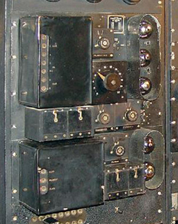
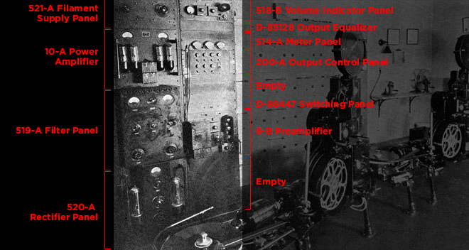
Since finding the photo of the backwall of the projection room during Hell's Angels, we have identified all of the components in the amp racks, and list them here in the interest of full disclosure. We believe that an additional rack containing the 41-A, 42-A and 43-A amps are out of the shot on the left.
LEFT RACK:
521-A Filament Supply Panel: Converts incoming 110 volt A.C.
to 10 volt A.C., sending it along to the filaments of the 10-A power amplifier.
10-A Power Amplifier: Receives audio signal from 8-B preamplifier. Input impedance of 4000 ohms; sends signal to speakers. Rated power output of 19 watts with a 500 ohm impedance.
519-A Filter Panel: Receives 750 Volt D.C. from the 520-A Rectifier Panel and filters it, sending 750 Volt D.C. plate current to the 10-A Amplifier; sends 130 Volt D.C. plate current to the 8-B Amplifier; sends 130 Volt D.C. plate current to Film / Disc Preamps on the sound dummies; sends 350 Volt D.C. plate current to the 8-B Preammplifier.
520-A Rectifier Panel: Converts incoming 110 Volt A.C. to 750 Volt D.C., and sends it along to the 519-A Filter Panel.
518-B Volume Indicator Panel: An output measuring device, with an onboard amp to run the VU meter.
D-85128 Output Equalizer: This unit is a "D-Spec" (Western Electric gear with a "D" prefix indicates original issue) filter of a inductance and a conderser, used to filter scratches over 5,000 cycles coming from the turntables.
514-A Meter Panel: Used to monitor filament and plate current to units in system. Used telephone-style plugs to patch into jacks on different components. Plate current levels displayed on left and center meters, filament current displayed on right meter.
200-A Output Control Panel: Recieves audio signals from the 10-A, and splits them to the individual horns behind the screen, and to the booth monitor horn.
D-88447 Switching Panel: Allowed switching between the film / disc inputs and the non-synchonized turntable.
8-B Preamplifier: Receives incoming audio signal from dummies, amplifies it and sends the signal on to the 10-A power amplifier. The input impedance is 200 ohms, the output impedance is 4,000 ohms.
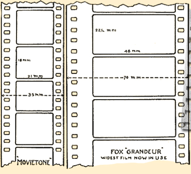
Fox Grandeur
The very next film to play at the Chinese after Hell's Angels, premiering October 2, 1930, was yet another experiment in motion picture presentation and showmanship. The Big Trail had been photographed in a 70mm format called "Grandeur." The entire film had also been photographed in conventional 35mm, since there was no way to print-down the Grandeur footage to 35mm. And besides, they were different shapes, with Grandeur having an aspect ratio anywhere from 1:2 to 1:2.13.
LEFT: Standard 35mm sound film and 70mm Grandeur film dimensions. From the American Cinematographer, February, 1930. "Seventy Millimeters: The First of the New Wide Film Processes Reaches Production," by William Stull, A.S.C. Courtesy of the American Widescreen Museum, provided by David Mullen. ABOVE: Recreation frames from The Big Trail, produced by Fox Films, 1930. This example shows the arrangement of sprocket holes and the Western Electric optical soundtrack.
Most of the Hollywood studios experimented with widescreen during the early 1930s. Fox had made a group of shorts and a couple of feature films in the Grandeur process in 1929-1930, but only three theatres could play the 70mm prints: The Roxy Theatre in New York City, the Carthay Circle Theatre in the Mid-Wilshire section of Los Angeles, and Grauman's Chinese in Hollywood. Many of these films (especially the Grandeur versions) are now considered "lost."
Historians argue over just how many Simplex Grandeur projectors were actually built — 7 to 10 of them. There is a theory that 3 Super Simplex Grandeur projectors were installed at the Carthay Circle Theatre in Mid-Wilshire for a Grandeur engagement of a Fox Film called Happy Days in February, 1930, and that these very projectors were taken out of the Carthay Circle and installed at the Chinese for The Big Trail engagement in October of that year.
ABOVE: Fox Carthay Circle Theatre, Los Angeles, California. Super Simplex Grandeur 70mm projector, 1930. From Recording Sound for Motion Pictures edited by Lester Cowan, AMPAS Publications, 1931. Courtesy in70mm.com. RIGHT: Super Simplex Grandeur Projector. From the collection of Carey Williams. Courtesy in70mm.com. Precious little is known about this projector, but the turreted lenses suggest it is capible of running both 35mm and another wide guage format.
What became of the projectors after these engagements is a total mystery. Projector collector Carey Williams owns what is thought to be a Simplex Grandeur projector, but it is unavailable for inspection. It is believed to be a dual 35 / 70mm Grandeur machine, which would account for its lens turret, or it might be for any of the competing wide-film formats raging through Hollywood at the time.
The Chinese seems to have changed little for Fox Grandeur. Since the screen didn't reach the full width of the now pylon-less (see above) 65 foot-wide proscenium, none of the theatre's sightlines were compromised, which would not be the case for many theatres during the widescreen boom of the 1950s.
Grauman's Chinese Theatre, Hollywood, California. 1930. Auditorium showing position of projection room, and 1:2.13 Grandeur screen 23' x 50.' Drawing by Kurt Wahlner.
Western Electric Wide Range System
While the camera engineers were fiddling with 70mm, audio engineers were doing what they could to improve movie sound. Western Electric began with trying to improve the range of frequencies which could be recorded during production. Beginning with the film Rain (which played the Chinese in 1932), the "Wide Range" system was employed, where only moving-coil microphones were used on set, with the signals being divided according to low, medium and high frequencies, processed individually, then recombined for recording on film.
As the recording of sound itself improved, there was also a focus to improve the sound quality heard in the theatre. The Chinese only had the 12-A loudspeaker array trying to replicate the entire frequency range, but it was not doing a terrifically efficient job with the high or low range.
To help with this, the first forms of equalization were brought to the amplifiers. We know this today as "bass" and "treble" control. It was now possible to fiddle with these two controls until the soundtrack sounded — better.
An improved soundhead was also developed, the 206, which attempted to reduce flutter (fluctuations in the film passing smoothly over the sound reader), as well as trying to get more detail from the optical soundtrack itself by reducing the slit of light passing through the film — the smaller the slit, the more details are transmitted.
Unknown Theatre, circa 1933. Western Electric Wide-Range Sound System set-up. 15A speakers above baffle containing tweeters at top, center. woofers at the bottom.
But there was more. Western Electric engineers designed a small horn speaker, which would handle frequencies from 3,000 to 10,000 Hertz (a tweeter), as well as 18 inch-cone loudspeakers on a 4 by 8 foot baffle for frequencies from 40 to 300 Hertz (a woofer). Combine all this with the older 12-A speaker used for the mid-range (300 to 3,000 Hertz) signal (which it was reproducing fairly well), and there you have it: a three-way speaker.
The Bostwick 597ATweeter.
The "passive crossover" was invented, which divided the audio signal into the desired frequency categories for each speaker after amplification. In larger theatres like the Chinese, multiple sets of amps / crossovers / speakers could be used for more volume. The crossover networks resided on the speaker towers backstage. All of this became known as the Western Electric Wide Range Sound System.
At the Chinese, the speaker rig was probably placed in the old speaker cabinet, and suspended in the same manner, since stage presentations were still being produced.
The first film to play the Chinese with the Western Electric Wide Range Sound System was Warner Bros.' Gold Diggers of 1933, premiering June 2, 1933, which seems to be fairly early in the rollout of the system. The supervising engineer for this installation was Frank N. Murphy.
Plaques were hung up in the theatres where the system was installed, informing patrons that the Wide Range System was one more step in the march of progress. It read:
1920: Phonograph
1926: Western Electrical Sound System and Electrical Phonograph
1933: Western Electric Wide Range Sound
Time marches on! By October 1934, The Wide-Range System was in over 1,000 theatres in the U.S.
Western Electric Wide Range lobby plaque, 1933. Reproduction, 1994. 12" x 18." This sizable display was hung up by theatres who had installed the "thrilling warmth of Wide Range Sound!" It is not known if the Chinese displayed one.
Enlarging the Projection Room
No one knows for sure, but sometime during the 1930s, the projection room had an expansion in order to utilize more spotlights. The walls of the room were moved as far out as the boxes flanking the room would allow, while large ports were drilled though the pilasters.
This expansion is therefore the reason that the two statues originally close to the projection room disappeared. Later photos of the theatre show that these extra ports were filled in, but it is unknown when — perhaps during the conversion to CinemaScope in 1953. Perhaps this occured when the projection room area was turned into VIP seating in 1959-1960.
Grauman's Chinese Theatre, Hollywood, California. Additional projection room spotlight windows, circa 1933.
Grauman's Chinese Theatre, Hollywood, California. Projection room ports, circa 2001. Photograph by Mike Renlund.
Photos taken of the theatre after the 2001 remodel show a pronounced discoloring of the pilasters where the ports had been, and these discolorings survived the 2013 IMAX® remodeling. The shafts of the pilasters have since been covered over with sound deadening material, sometime during 2014.
The Golden Age: 1933-1949
At this point, Grauman's Chinese Theatre enters into a "Golden Age," where the movies were the number-one entertainment in America, resulting in the studios who made them becoming very profitable. Grauman's Chinese, the glamourous flagship venue of the Fox West Coast Theatres chain (itself owned by 20th Century-Fox and the Skouras Brothers) and under the continuing management of Sid Grauman, played host to a large number of Fox films, rotating with product from Metro-Goldwyn-Mayer and the occasional offering from United Artists. Theatres during this time tended to play pictures from the studio who owned them (or had strong business ties to).
Audiences were faithful, business was very good, and the writers and directors of the Hollywood studio product were free to concentrate on developing the arts of storytelling and design — all within the bounds of the 1:1.33 Academy Ratio with mono sound — in addition to the strictures of the Hayes Office.
However, as had been shown in the past, the desire to improve the 1:1.33 / mono experience was strong. The introduction of three-strip Technicolor, better, faster lenses, fine grain film stocks, improvements to microphone design, recording techniques, and special effects resulted in one Technical Achievement Oscar after another.
Grauman's Chinese Theatre, Hollywood, California, July 17, 1937. Crowds line up for an early evening performance of Captains Courageous with second feature, The Great Hospital Mystery.
As moviegoing increased during World War II, by mid-1945 all the M-G-M product was showing at the Egyptian Theatre down the street. The Chinese continued to show mostly the expanding output from the 20th Century-Fox studio, but FWCT took up the slack from M-G-M's exit by booking lesser films from other studios like Columbia, UA, Universal and others.
All remained well until, after World War II, film attendance dropped off, then another blow: television. Looking at the Chinese Theatre playdate pages for the early 50s shows a lackluster parade of double features (along with a sprinkling of admittedly classic films from the Fox studio), all of which played short engagements. The need to pump new life into the movie-going experience (especially after the introduction of the Cinerama process in September of 1952) is obvious. Along with the death of Sid Grauman in March of 1950, a Golden Age had passed, and a new one would (hopefully) open.
Dissatisfaction with
Western Electric Wide-Range Sound
The Western Electric designed "Wide-Range" system, with its three-way speaker set-up was revealed at the Chinese for the first time providing the soundtrack for Gold Diggers of 1933 in June, 1933. Audience members were encouraged to experience the "thrilling warmth" of the system, and indeed, it must have seemed a great leap forward — unless you were an audio engineer.
The dissatisfaction with Wide-Range stemmed from the fact that, in order to recycle the old large 12-A horns and use them as the midrange speakers rather than design something new, WE had introduced listeners to a new phenomenon: phase distortion. It is simple really. The newer woofers and tweeters were small, compact units. The response from the driver out through the smaller speaker cones was very quick. The large horns asked the sound emitted from the drivers to travel 12 feet before it exited the horn.
So what you heard was high and low end sounds, with the midrange arriving — late. Not quite like an echo chamber effect, but "earwitness" accounts recall that if someone say, was tap dancing onscreen, you would hear two taps, rather than one. Not good. Especially in an acoustically "live" boomy room like the Chinese, with all of its hard surfaces.
Developing the Shearer Horn
This problem must have been especially apparent to Douglas Shearer (1891-1971), head of the Sound Department at the Metro-Goldwyn-Mayer studio, when he came out to the Chinese to see the premiere of Dinner at Eight, on August 29, 1933. Dinner at Eight was the next film at the Chinese to play with the Wide-Range system after Gold Diggers of 1933, and the phase distortion must have been apparent to him.
John Hilliard (1901-1989), was born and raised in Minnesota, and had been recruited by United Artists in 1927 to be in charge of that studio's sound department, where he wrestled with the Western Electric sound gear. His dissatisfaction with the WE status quo attracted the attention of Shearer at M-G-M, where Hilliard went to work in 1933. Initially, Hilliard was put on a project calling for a review and redesign of the chain of amplifiers used to record sound at the studio, correcting a "phase shift" which distorted everything, but most egregiously, speech — dialog.
After hearing Dinner at Eight at the Chinese, Shearer put Hilliard in charge of a new project: the design of an improved, two-way speaker which would be smaller, better sounding and less expensive and cumbersome than the Wide-Range system. Shearer believed that such a speaker could make films sound better throughout the country, and since M-G-M now had the best soundtracks in the industry, the superiority of the M-G-M product would be demonstrated once again.
DAR Constitution Hall, Washington, D.C. Harvey Fletcher stands before one of the three Fletcher Horns used in a demonstration concert on April 27, 1933. Photo courtesy Retro Vintage Modern Hi-Fi.
Hillard had been aware of a special demonstration project going on at Bell Labs (a division of Western Electric), headed by Harvey Fletcher (1884-1981). The Fletcher Horn System had been designed to try to replicate an orchestra to the point where an audience wouln't be able to distinquish the real thing from the reproduction.
Fletcher and his team (including Edward C. Wente and Albert L. Thuras) had developed a two-way system for the speakers. The low end of 40 to to 300 Hz, would be reproduced by a huge 20-inch woofer inside an enormous folded path cabinet. The higher range would be handled by a driver purposely engineered differently than the WE 555 driver — only this time, it was placed at the rear of a "multi celled horn" which will be explained in more detail below. The higher range was from 300 to 15,000 Hz!
Aditionally, the Fletcher System would pick up the orchestra via three moving coil microphones, then this signal would be reproduced by three of these two-way speakers arrayed across the stage at a remote location. The total wattage for the three speakers: 450 watts!
The Fletcher System had been demostrated to the public on April 27, 1933, with a live transmission of the Phildelphia Orchestra, playing at the Academy of Music in Phildephia, with the signals from the three microphones being carried over dedicated Class A telephone lines, then delivered to three Fletcher Horns onstage at the DAR Constitution Hall in Washington D.C., where the orchestra's conductor, Leopold Stokowski (1882-1977), oversaw the mixing of the transmitted performance. The audience (invited members of the National Academy of Sciences) were wowed!
So M-G-M's John Hillard contacted Bell Labs and asked if it would be possible to turn the Fletcher System into something which could be used in motion picture theatres. Bell turned it over to Western Electric, who said they would look into it.
Nothing happened.
A year later, in 1934, Hilliard learned to his dismay that WE had done nothing with his request. Miffed at Western Electric's behavior, Hilliard and Shearer realised they were going to have to do something else.
Douglas Shearer (right), with producer Hunt Stromberg at the March 5, 1936 Academy Awards banquet, held at the Biltmore Bowl in the Biltmore Hotel, Los Angeles, California. Photo via www.erbzine.com. This is a shot of Shearer and the Oscar he received for the sound work for the film Naughty Marietta.
John Hilliard, photograph probably taken mid-1950s. Photo courtesy of Todd White, via www.audioheritage.org.
Here is where Jim Lansing (1902-1949) comes in. Lansing and his business partner Ken Decker had met while both were working in Salt Lake City. Since 1927, Lansing Manufacturing had been making jillions of radio set speakers for the Jackson-Bell Radio Company after moving to Radio Row just south of downtown Los Angeles.
Lansing and his chief designer, Dr. John F. Blackburn, had produced a very impressive 15-inch cast-frame woofer, which Hillard had heard about because Blackburn used to be research buddies with Hilliard's wife Jessamie — Blackburn had become interested in film sound by knowing John Hilliard.
Talk about being in the right place at the right time and being prepared: When Hilliard met with Lansing and Blackburn, the two had just returned from seeing the WE Wide-Range system on exhibit at the Society of Motion Picture Engineers (SMPE) show at the Knickerbocker Hotel in Hollywood. After talking about what they didn't like about the system, the conversation drifted toward how they should all get together and make something along the lines of the Fletcher System — only a bit more practical. This would become the Shearer Horn.
The high end would be handled with a compression driver combined with what they called a "multi-cellular" horn. The lower end would consist of the Lansing 15-inch cone speaker(s) either on a baffle, like the Wide-Range system, or a horn, like the 12-A.
The Lansing-designed 284 compression driver turned the design of the WE 555 inside out: the field coil is still a big circular magnet with a constant charge, but now, the voice coil slips in and out of the center of the ring. At the back of the voice coil itself is a much larger aluminum diaphragm which is in a constricted space, so it very efficiently pushes the sound waves through the hole in the middle of the magnets. This design could make lots of noise.
The compression driver was used with a multi-cellular horn. We have all seen these horns at some point in our lives, but why are they like this? The answer is interesting too.
Lansing Multicellular Horns. From "Lansing Sound Equipment" brochure, Bulletin #6, Lansing Manufacturing Company, Los Angeles, California, circa 1938.
Ask any horn player why the bell on their horn is round, and they will tell you: any other shape would distort the sound waves coming out. Fair enough. Now, imagine you are up behind the screen looking down at the orchestra floor at the Chinese. In what shape is the seating? Pretty horizontal, isn't it? In order for the sound waves to reach all of those people arranged in a somewhat shallow semi-circular bowl, you needed speakers which would point in those directions, right?
Trouble is, if you tried to cover this area with a horizonal-shaped horn, you would be distorting the sound waves horribly. A multi-celled horn solves this problem by having nearly round (okay, square) horns pointing across a wide spectrum. Additionally, the highest frequencies narrow over distance, so the multicellular horn helps prevent this. With the compression driver's ability to produce huge sound waves, and the multi-cellular horn's ability to allow the waves to keep their same shape while spreading it all over the audience while remaining perfectly in phase, well, this was a great improvement.
The bass speaker's driver was called the 15XS field coil driver by the Lansing staff, but Hilliard couldn't decide on what sort of horn configuration to use. According to audio lore, it was around this time that both Western Electric(!) and RCA became aware of Shearer's project and wanted in. RCA's Harry Olsen (1901-1982) suggested using a "folded" horn design they had been developing, which had the advantage of having a long "column" while conserving space — an important consideration, since movie theatres were no longer being equipped with stages anymore.
By 1935 a prototype was ready to test in theatres. The Chinese could very well have been one of these test theatres, due to the fact that it was the premiere showcase for M-G-M product in Los Angeles at that time, and also because of the auditorium size and acoustical qualities. The two pieces of the puzzle, the upper range horn and the lower proved to pair together seamlessly, giving the unit an overall bandwidth of from 50 to 8000 Hz. Despite the need for a long horn for the bass speaker, the measured phase difference between the two drivers was only 1 millisecond apart. Wow!
Subsequent tests around the country impressed the executives at Loew's Inc. (parent owner of M-G-M) enough to order 150 "Shearer Horns" for various theatres in the Loew's chain. It was arranged that Western Electric would make 75 units, while RCA would make the other 75. Both companies sub-contracted with Lansing Manufacturing to make all the drivers. Both companies also arranged to have the right to market the "Shearer Horn" design to theatre owners all over the world. Western Electric initially called the speaker the "Diphonic," as part of their "Mirrophonic" system, while RCA marketed it under their "Photophone" brand. Lansing sold the design as The Shearer Horn, which they offered in a number of different cellular horn configurations, depending on the width of the theatre they were installed in.
Diagram of Shearer Horn prototype. 1935. Drawing via www.filmsound.org.
Lansing Shearer Horn
Lansing Manufacturing was fortunate to have become involved with the development of the Shearer Horn, as Jim Lansing and his business partner Kenneth Decker had a fantastic new product they could sell to theatre owners everywhere. Just exactly when the Shearer prototype was pulled out of the Chinese and sent back to M-G-M is unknown; since Western Electric didn’t roll their “Mirrophonic Sound” system out until October 1936, and the “Diphonic” speaker joined the RCA Photophone system in January 1937, it seems that Lansing got the jump on both of these electronic behemoths. And why not? It’s the early bird and so on. . .
The exact date is unknown — not even the historians who follow audio history closely know for certain, as records seem to have vanished, but what is known is that Lansing Manufacturing Company was certainly out there, selling Lansing Shearer Horns by early 1936, citing Grauman’s Chinese as being “A Lansing Horn Equipped Theatre.” We are figuring that Lansing secretary / treasurer Ken Decker convinced Fox West Coast Theatres to install the Lansing Shearer Horn at the Chinese in advance of their formal marketing of the product, so that they could claim the Chinese as a premiere user in their initial advertising. FWCT was willing to go along with this, mainly because by this time (late 1935), relations between the theatre chain and WE / ERPI had been completely severed (see below). There was another reason: after having the Shearer prototype in the house for six months or more, who wanted to go back to the Western Electric Wide-Range speakers?
Lansing Manufacturing Company, Los Angeles California. Lansing Sound Equipment promotional brochure, beginning early 1936; 9.5 inches x 11.5 inches. Lansing sent their promotion brochure out in a folder with numbered "Bulletins" inside, which allowed the brochure to be updated as new products were introduced. The Shearer Horn Bulletin is No. 2. This example was sent out by Ken Decker in May 1938, to a theatre owner in Eugene, Oregon, named Don L. Hunter.
So the Lansing Shearer Horn was hooked up to the Western Electric 41-A, 42-A, and 43-A amps, and there wasn’t a damned thing in the world WE could do about it.
For the bass, the Lansing Shearer Horn had the 15XS field coil driver, which was an extremely sturdy, “efficient” (low consumption of power), highly precise driver using a seamless paper cone attached to a 2-inch voice coil. For the high end, the 285 compression driver was used, which also used a field coil with a 2.8-inch flat wire voice coil attached to a 2.84-inch aluminum diaphragm (see comparison diagrams below). The throat at the front of the driver was 1.5-inches.
Lansing Manufacuring Model 15xs Low Frequency Speaker. Introduced in 1935. From Lansing Sound Equipment promotional bulletin number 5, circa 1936. 15 inches diameter, 9 inches high; 27 pounds.
Lansing Manufacuring Model 285 High Frequency Speaker. Introduced in 1935. From Lansing Sound Equipment promotional bulletin number 6, circa 1936. 6.5 inches diameter, 5.24 inches high; 26 pounds.
A problem with the compression driver was that fact that points along the diaphragm to the throat were not equal. Additionally, sound waves escaping the compression chamber cancelled each other out. Western Electric had solved this problem by inserting what has since come to be called a “phase plug” into the throat of the driver, forcing the waves along precisely equal paths as they exit the driver and go (in the case of Shearer Horn designs) into the multi-cellular horns.
Western Electric
555 Receiver - 1933
In the 555 receiver, the first phase plug design consisted of a diaphragm-fitting pyramid shape suspended in the throat. Air waves created by the vibrating diaphragm escaped through a circular slit — with the path widening upon exit. Since all the waves only had this one path all around the plug, this was considered a pretty good solution to the problem.
However, it may be seen that the path from the center of the diaphragm has a longer exit path than do the edges. What could we do about that?
= Field Coil (constant charge)
= Voice Coil (fluctuating charge)
= Diaphragm
= Phase Plug
Western Electric
Fletcher Horn Driver - 1933
In the Fletcher Driver, the pryamid shape was spread over the much larger diaphragm, but it was made up of wider and wider brass bowl-like shapes, ingeniously tapered, allowing each path a wider exit opening.
All of the segments of this phase plug were suspended in the throat by means of small pins which were inserted between the sectors at 120 degrees from each other.
The compression chamber behind the diaphragm was vented, with a heavy mesh covering the openings.
This design was used by Lansing for the initial Shearer Horn prototypes — the 284 driver (see above), but Western Electric objected that its patent was being infringed, so Lansing would have to come up with something else.
= Field Coil (constant charge)
= Voice Coil (fluctuating charge)
= Diaphragm
= Phase Plug
Lansing Manufacturing
Model 285 Driver - 1936
So what Lansing's Dr. Blackburn did was to take the pryamid shape, and to cut 20 radial tapering slits from the outside almost to the center — like wagon wheel spokes.
This design would allow a greatly expanded airflow outward, and since the outer edges of the diaphragm could use a little help, each slit was ever so slightly wider at the edges, allowing better flow.
This incredibly complex shape was machined at Lansing out of brass, and represents a high-water mark in precision machining.
Alas, after Western Electric went out of the theatre speaker business, Lansing was free to revert to their Model 284 driver design, which utilized the Fletcher Horn phase plug design.
= Field Coil (constant charge)
= Voice Coil (fluctuating charge)
= Diaphragm
= Phase Plug
Since the Chinese was a rather large theatre, the Lansing Shearer Horn there had four 15SX speakers in two folded bass cabinets, flanked by a baffle wall. The multi-cellular horn on top was in the 3 x 5 configuration, with two 285 drivers in a “Y” configuration at the rear. Each of the cells in the horn covered 17 degrees, and so, this would have covered 85 degrees in width and 51 degrees in height. The frequency bandwidth of the unit was 50 to 10,000 Hz. The entire unit measured 145 inches wide x 123 inches high x 33 inches deep. The bass cabinets were mounted side-by-side as better horizontal dispersion was needed, since the Chinese has no balcony. The unit was mounted on a platform which placed the multi-cellular horn just slightly above the center of the screen.
The Shearer Horn System, Lansing Manufacturing Company, Los Angeles California. Introduced in late 1935. 145 inches wide, 123 inches high, 33 inches in depth. Photos courtesy of audioheritage.com. This Shearer set-up is probably what was installed at the Chinese in late 1935, with 2 bass cabinets flanked by a baffel, while the 3 x 5 cellurlar horn is outfitted with two Model 285 drivers in a "Y" configuration. The Lansing crossover network is attached to the right rear of the bass cabinet, just to the right of the vertical venting slots.
Dissatisfaction with Western Electric
Western Electric / EPRI trade ad explaining ERPI service contract fees. From the March, 1932 issue of International Projectionist, Volume II, Number I, page 7.
The Shearer Horn was a significant development, but when one reads between the lines, it happened outside of the auspices of Western Electric. The reasons for this are many, but a brief rundown is in order.
Originally, Western Electric made both Movietone and Vitaphone soundreaders, amps and speakers, while RCA made their Photophone brand sound on film soundheads, amps and speakers. Both companies leased the equipment to theatre owners and charged a “service fee” for technicians to come out and maintain the equipment, replace burnt out lamps and so on. With both companies, the term of the lease was ten years.
To begin with, theatre owners didn’t like this sort of thing at all. They chaffed having to pay the “servicing” fees on gear which was running perfectly well (thanks to the efforts of in-house (and often Union) projectionists. Additionally, RCA felt that their Photophone system was being unfairly locked out of the marketplace, a situation RCA head David Sarnoff couldn’t allow to continue.
In December 1932, RCA announced that they would now sell Photophone systems to theatres (with easy time payments if needed), and only require payment of the service fees for half of the term of the loan, say, 18 months on a three-year payment plan on the equipment. After that, it was yours, free to maintain as you saw fit. Pre-existing RCA leased equipment would have three years to go on their service contracts.
WE / ERPI’s response: monolithic silence. Since March 1932, ERPI had been engaged in a P.R. campaign explaining to theatre owners how the EPRI service fees were fully justified, combatting the impression that ERPI was gouging people. With RCA’s move, WE / ERPI didn’t want to change any of their policies because of a huge lawsuit they were involved in with Warner Bros. Lawsuits were everywhere. In late 1933, 102 WE equipped theatres in New York City banded together to sue for a reduction in the servicing fees.
RCA Photophone trade ad announcing RCA obtaining serviceing contracts for the Fox Theatres chain. From the October, 1938 issue of International Projectionist, Volume XI, Number 4, page 9.
Amazingly, Western Electric’s EPRI decided to double down on service fees. In December 1934, they revealed plans to service the entire theatre — projection and sound, but also, screen, seats, carpets, heating and cooling — the works. They started calling this “cellar to roof” contracts. It was widely rumored that RCA would have to develop a similar contract “in defense” to remain competitive. If the theatre owners didn’t like the idea of ERPI’s service fees for just the sound system, imagine what they thought of this idea! The next month, in January 1935, Warner Bros. cancelled all of the ERPI service contracts in all of their theatres. Loew’s Theatres canceled the contracts in 64 of its New York City area theatres, while threatening to discontinue the contracts chain-wide. The theatre supply companies were urging for a Federal investigation. In March 1935, it was reported that Fox West Coast Theatres, of which Grauman's Chinese was part, was dropping their ERPI servicing contracts. The attitude of the theatre owners toward ERPI seems to have been summed up in two words: “Sue us.”
In 1935, theatres in Los Angeles with IATSE contracts, seating over 2,000, were required to have two operators per shift, each one making $2.75 per hour.
In September 1935, ERPI announced that it was abandoning its “Cellar to Roof” service plan. In October, Western Electric was in the hot seat, as the Federal Trade Commission was looking into parent company AT&T’s business practices, which included an investigation of the WE / ERPI film sound business. In the courts, RCA brought suit against WE / ERPI for restraint of trade in regards to equipping the film studios. WE / ERPI agreed to a settlement with RCA, making a payment of $3 million; they agreed to the non-exclusivity of their theatrical service contracts (which would allow RCA technicians to service WE equipment), and agreed to stop bad-mouthing the RCA gear around the studios. Earlier, it was revealed that WE / EPRI settled their lawsuit with Warner Bros. for a whopping $4 million. It was also revealed in the FTC hearings that ERPI had made a $9.4 million profit since 1927, so it then appeared to one and all that ERPI was gouging theatre owners in order to pay for the lawsuit settlements. Another problem was the fact that WE had not developed any new equipment to sell to theatres, and so WE / ERPI only had the servicing fees and selling replacement parts as revenue streams coming in — no wonder they wanted to get in on the Shearer Horn project!
Fox West Coast Theatres' parent company, National Theatres, signed a contract for RCA technicians to service their WE sound gear. It is believed that RCA Photophone sound heads and amplifiers are installed at the Chinese in February 1937 (see below), along with the Carthay Circle Theatre in Mid-Wilshire. By January 1938, the RCA technicians had joined the IATSE, since they were technically operating in the Union-controlled space of the projection room.
The meltdown with Western Electric and ERPI is one of the most puzzling moves in the history of film technology, recalling the Edison / Patent War battles of the Silent Era. They must have felt that they were in a strong position to dictate the terms and costs of supplying sound equipment to the nation’s theatres. David Sarnoff’s RCA didn’t quite see it that way; theatre owners all across the country agreed with him. Western Electric would leave the theatrical film sound field altogether, but we are getting ahead of ourselves.
RCA Equipment Comes to the Chinese
And so, in February of 1937, the Western Electric sound system was pulled out of both Grauman’s Chinese and the Carthay Circle Theatre in Mid-Whilshire. RCA soundheads and amplifiers were installed to take their place. As we have noted, this was the climax of a period of tension between Western Electric-equipped theatres and Western Electric itself, with the result being that Western Electric and their ERPI unit would get out of the business of movie house sound systems altogether before long.
Grauman's Chinese Theatre, Hollywood, California, week beginning February 3, 1937. Colored postcard photo, taken while You Only Live Once and Dangerous Number were playing.
The RCA “Photophone” brand had been around for almost as long as the Western Electric sound systems had been. The founding of RCA, the Radio Corporation of America, lies in the appropriation of all radio technology by the U.S. Government during World War I. Congress had failed to extend government control over radio technologies after the war, prompting the General Electric Company to begin selling parts to other companies around the world, including the Marconi Company of Great Britain, headed by David Sarnoff (1891-1971), which had a subsidiary in the U.S.
Since American radio efforts were in danger of being eclipsed by the British, the U.S. Army and Navy did not care for this idea. They suggested that if General Electric purchased the American branch of the Marconi Company, the U.S. Government would grant this new entity exclusive right over long-distance radio communications. The new entity was formed with other assets (including Westinghouse) and called the Radio Corporation of America on October 17, 1919, placing lawyer Owen D, Young (1874-1962) as CEO, with Sarnoff as general manager.
Sarnoff pushed to make radios, which would broadcast “programs” from a radio station, to an “audience.” To make a very long story short, RCA began to make and market radios for home use. The profits were used to purchase a collection of early radio stations, forming the National Broadcasting Company, NBC, in 1925. By 1929, Owen Young was out, and Sarnoff rose to the presidency.
At the close of World War I, a General Electric engineer named Charles A. Hoxie (1867-1941) had developed a method to record sound waves onto movie film. He just thought movie film would make a good medium for the recordings, which, by 1921, were pretty decent. They called it the Pallophotophone. Catchy, ain’t it? Sound signals were sent to a tiny mirror, which would oscillate. Light bounced off the mirror would then shine down through a slit onto 35mm film, thereby making a “picture” of the sound waves. This became known as a “variable area” soundtrack. On playback, light was shone through the soundtrack, which would send its impulses to a photoelectric cell (as in the Movietone and Western Electric systems), which would then send signals to amplifiers and speakers.
Charles A. Hoxie, circa 1922. Form the John P. Harribgton Papers of the National Anthropological Archives of the Smithsonian Museum.
David Sarnoff, circa 1922. Via Wikipedia.
Joseph P. Kennedy, no date. From www.mchenrycounty1981.com.
By the time RCA became involved Sarnoff could see the use for this immediately. They reconfigured the system so that the mirror was being manipulated not by sound waves directly, but through the electromagnetic signals coming from a microphone. They called this new system Photophone. There was a problem, though: Western Electric had gotten to the market first, with their sound-on-disc system, used by the Warner Bros. / First National combination, their own sound-on-film system, while the Fox-owned “Movietone” sound-on-film system, was only for film production, not exhibition.
In a complex series of events, by late 1928, Sarnoff, working with Joseph P. Kennedy (1888-1969), had purchased the Keith-Albee-Orphuem circuit of vaudeville theatres, and a Hollywood-based studio, the Film Booking Office (FBO). With a studio to make films in, and theatres to show them in, and RCA’s Photophone to give them sound, the new studio, Radio-Keith-Orpheum, or R-K-O, would make only sound films. RCA Photophone was now in business in a big way, equipping their theatres, and making what were considered innovative sound films.
RCA offered theatres optical sound heads, amplifier systems and loudspeakers. At the time the Chinese installed the RCA Photophone gear, only the soundheads and amps were needed, since the Lansing-brand Shearer Horns were behind the screen.
RCA Photophone trade ad featuring the new MI-1040 rotary stabilizer soundhead. From the August, 1935 issue of International Projectionist, Volume IX, Number 2, page 3.
In order to read and reproduce the information on an optical soundtrack with the fullest fidelity, designers were always on the lookout for ways to improve the design of the soundhead doing the reading of the track. In honor of the opening of New York City's Radio City Music Hall in December 1932, RCA had developed a soundhead with a difference: a rotary stabilizer. That sounds technical, doesn't it?
Up to this point in time, film would travel through a projector via a series of interconnected sprockets, all (expect the intermittent, which pulls the film one frame at a time) spinning at the same speed. The soundhead was part of this. The film was pulled through the picture gate by the intermittent, and then, on to the lower sprocket of the projector. In the soundhead, there was another sprocket to pull it smoothly through another gate (like a shorter version of the picture gate up above) where the beam of the exciter lamp would shine through the soundtrack and onto the photo-electric cell.
In 1932’s MI-1020, and now in 1935 with the MI-1040 soundhead, the sound gate was replaced with a smooth drum, which was connected to a very finely balanced flywheel housed in oil. The film passes over this drum, called a rotary stabilizer, and which spins only by the motion of the film itself. Beyond the stabilizer there was still a sprocket to propel the film, but at the point of scanning, the motion of the film was now isolated from the drive mechanics of the rest of the projector. The MI-1040 virtually eliminated "flutter" (distortion caused by vibrations in the system). This became to projectionists what finely balanced turntables became to hi-fi fans years later.
Regent Centre, Christchurch, Dorset, England, United Kingdom. Projection Room. RCA Photophone Model MI-1040 soundhead. Introduced in 1935. Photo John Thornley, courtesy Primolux Projector Restoration.
RCA Photophone Model MI-1050 soundhead. Introduced in 1938. Photo by John Thornley, courtesy Primolux Projector Restoration., Christchurch, Dorset, England, United Kindom.
Since the motor driving the projector and the soundhead was actually attached to the front of the soundhead, vibration from the motor could always transfer to the the sprockets in the soundhead itself. Every effort was made to ensure stability: all of these sections were bolted together very firmly. The motor was attached to the MI-1040 via a coupler, which helped to minimize vibration. On the top of the coupler was an “inching" wheel, which would allow slow advancement of the film path, which would help operators get the picture in the gate correctly.
In 1938, RCA introduced the MI-1050, which placed a heavy flywheel on the motor shaft. This had the effect of starting rotation more smoothly; additionally, the extra weight made the unit operate more smoothly while at running speed. The flywheel also helped when it came to advancing the film path: one could simply turn the big flywheel.
The efforts of RCA to develop the rotary stabilizer did not go unnoticed by Western Electric, who as we mentioned, were involved in the Shearer Horn project. In October 1936, WE rolled out their “Mirrophonic” system, which included a new soundhead with rotary stabilizer, new amplifiers, and their version of the Shearer Horn (using a variant of the Fletcher Horn phase plug).
Regarding the RCA amplifiers which were installed in February 1937, not much is known. Not many of these units are still with us today. What we can say about them are features mentioned in the RCA advertising for this time frame, which go like this:
All AC powered, rack-mounted units.
Standard RCA vacuum tubes. Replacements "available anywhere."
Optional remote volume control allows adjustment of volume from within the auditorium — swell!
Separate voltage and power amplifiers. If power amplifier fails during a show, one could continue with voltage amps. We are assuming that the Chinese probably had an "A" amp chain, and a backup "B" amp chain in case of failure in the "A" chain.
RCA Photophone trade ad featuring RCA amplifier unit. From the September 1935 issue of International Projectionist, Volume XI, Number 3, page 6.
The Simplex E-7 Projector
Meanwhile, the Simplex projector had not been radically improved since 1930. By April of 1937, a new model, which was called the Simplex E-7, was placed on trial at the Loew's Capital Theatre at Broadway and 51st Street in New York City. The trial must have been successful, because by the following year, 1938, the Simplex E-7 was rolling out to theatres across the country.
A major design feature of the E-7 was its double-shutter system, which resembles the older projectors of the silent era like the Powers, with one shutter in front of the lens.
Simplex was playing catch-up with other projector manufacturers such as Century and Brenkert, who had developed double-shutters which rotated in opposite directions in an enclosure between the carbon arc lamp and the film gate. The idea was this: with a single blade shutter, the blade sweeps across the film in one direction only. With two blades, the blades would sweep across in two directions, revealing the film gate in much the way the eyes open, resulting in less time spent opening the shutter entirely. The faster opening time would produce a brighter picture onscreen.
Simplex E-7 Projector. Introduced in 1938. Catalog photograph showing Peerless Magnarc lamphouse, SH-1000 sound head, and Simplex Heavy Duty pedestal. Photo courtesy Tom Wilson via Flickr.
Typical silent projector single shutter diagram, showing how the film gate is opened and closed in one direction only.
Typical “double shutter” diagram, showing how the shutter opens across the film gate in two directions.
Dome Cinema, Worthing, West Sussex, England, United Kingdom. Projection Room. Simplex E-7 Projector with RCA Photophone Model MI-1050 soundhead. Photo by Sound Associates, via Twitter.
Simplex did not feel comfortable with merely replicating the Century-like design; what they did was to take their regular Super Simplex shutter design and place another enclosed shutter in front of the lens. This shutter would be connected with the rear shutter via a shaft, so it would spin in the same direction. This would act in the same manner as the others, because when the image exits the lens, it is inverted, and so the opening action is essentially the same.
Of course it was possible for the shutters to get out of sync, so operators had to make sure they were synced up correctly – one of those new-fangled pain-in-the-neck things, which did not endear the E-7 to the projectionists of the world. In fact, the E-7 works perfectly fine with the front shutter removed entirely, allowing for the usually larger and longer CinemaScope lenses introduced in late 1953, and this is how most E-7s are configured today – no front shutter.
One of the selling points of the Simplex E-7 was its “one-shot” lubrication system. Inside of the case, just below the lens barrel, was the spout for the oil system. One had to pump a spring-loaded handle to provide the pressure needed to flow oil throughout the system.
The E-7 Operator’s Manual states that, when the projector is new, the lubrication system’s pump operates every two hours of projector run time, requiring daily additions of oil. Then the system somehow lengthens the time between automatic pumpings, until an interval of 4 hours of run time is maintained for the rest of the life of the projector. At this point, the system required replenishment twice a week.
Despite the “One-shot” oiling system, the E-7 still required that the intermittent be oiled in a separate operation. The “drive” side of the projector contains an oil level indicator for the intermittent. Operators had to keep an eye on this, and fill it as needed. One also had to oil the projector’s governor from that side. Using Simplex Oil, naturally. And never while the projector is running.
RCA Photophone Model MI-9030 soundhead. Introduced in 1938. Originally in a theatre in Powhattan Point Ohio. Photograph by Tom Wilson, via Flickr.
We believe that the Chinese probably had three of these Simplex E-7 projectors installed in 1938, since the Chinese was the flagship of the Fox West Coast Theatre chain. The entire sound system was probably retained. The old Simplexes installed in 1930 could easily have been installed in some newly-opened Fox West Coast Theatre, such as the La Reina Theatre in Sherman Oaks, which opened in 1938.
We are also imagining that the Chinese would have been upgraded with the latest in — everything. In 1938, RCA brought out another soundhead, this one called the Model MI-9030. Apart from the radically different styling to the cabinet, this new unit had the motor’s drive shaft connected to the upper of the soundhead’s two drive sprockets. It also had the feature of having two exciter lamps mounted in a turret arrangement, so that if one blew out, one could pull up on the mount, turn it to the other bulb, and continue.
The End Comes to Western Electric / ERPI
You may very well be asking what happened to Western Electric and the gang at ERPI. Well, for one thing, they introduced their "Mirrophonic" system in October of 1936, but by that time, RCA had been pushing their system (with its version of the Shearer Horn) to exhibitors for two years, so when WE / ERPI brought the Mirrophonic system out, exhibitors generally said, "Yawn."
In 1938, everything blew up on the Western Electric / ERPI people. Years before in 1929, Warner Bros. had been expanding their chain of Vitaphone theatres. An aggressive bunch with lots of cash, they had become dissatisfied with the pace with which they were getting their theatres equipped for sound. Western Electric / ERPI had signed agreements to supply Warner Bros. and all the other major studios and most of their theatres with WE equipment.
Altec trade ad. From the January, 1938 issue of International Projectionist, Volume XIII, Number I, pages 2 and 3.
Caught in a bind, the Brothers Warner entered into an agreement with a company which was making sound systems developed by radio engineer Louis Gerard Pacent (1894-1952). Although disc-based, the Pacent system offered several advantages when compared with WE's Vitaphone, including most importantly, a lower price. Despite the fact that Pacent had licensed some WE technology to use in his system, WE / ERPI sued the company for patent infringement, and won a ruling in their favor in 1932. But it was a pyrrhic victory because, with the backing of Warner Bros., various parties who felt that they had been steamrollered by Western Electric and ERPI, eventually brought a move for anti-trust litigation to the attention of the U.S. Justice Department.
A 1938 consent decree was signed by Western Electric, the terms of which ordered them to divest themselves of their ERPI unit, and thus, out of the entire field of movie sound systems. Many of the technicians and engineers at WE were given stock options over the years, and these engineers decided to buy back their now-worthless stock, and were allowed to license (royalty-free) many WE designs, for $1.00. Most of these parties went off to form the Altec company, which would merge with Lansing Manufacturing (suddenly floundering and in trouble, due to the death of Jim Lansing's business partner Ken Decker) in December, 1941. The WE sound "monopoly" — if it ever existed — was broken. The industry would have to look to others for the next improvements in movie sound and projection systems.
RCA and the Academy Curve
With the demise of WE / ERPI, RCA suddenly became the lead player in movie sound systems for theatres. Others continued to make sound systems for movie theatres, but the RCA product had a clear technological advantage over the others.
Part of this advantage was RCA’s involvement with a project the Academy of Motion Picture Arts and Sciences had embarked on in 1938. The Academy was attempting to establish a standard for optical soundtracks, so that they would have a chance of sounding consistently, from theatre to theatre, and from studio to studio. An impossible task? Perhaps.
Tests were conducted using a 20-minute reel made up of dialogue and music samples from all of the major studios, played through Shearer Horn type loudspeakers in houses all across the country. After measuring the performance of all this material, what came to be called the “Academy Curve” was developed. The studios adopted a method of boosting the high end of the audio spectrum (pre-emphasis) in the mixing of the soundtrack, then, a properly calibrated playback unit would turn the boosted high end back down (de-emphasis), resulting in less background noise.
Since RCA had participated in the development of the Academy Curve, they were in a position to manufacture Curve-compatible equipment. In 1938, they began rolling out what might be called their “PG” systems, beginning with the PG-90 for small theatres, ranging all the way to the PG-142 for huge theatres. The Chinese is a very large theatre, so we are figuring the PG-142 system was installed.
RCA Photophone PG-142 Gear
There continued to be a focus on isolating the soundhead from vibration. Toward this end, RCA designed a new soundhead, the MI-9050. They did something which seems like a no-brainer, but for the time, it was another leap forward. In the soundhead, there had always been two sprockets. Before the sound drum, was the Constant Speed Sprocket, which was traditionally connected to the main projector drive shaft. After the sound drum was the Take-Up Sprocket, attached to the main shaft by a pulley.
In the MI-9050, this relationship was reversed: The main projector shaft was connected directly to the Take-Up Sprocket, with the Constant Speed Sprocket connected by a pulley. What this did was to isolate the Constant Speed Sprocket, thereby allowing for less vibration before the film passed over the sound drum. The improvement was considered so great that RCA called the unit its “Shock-Proof Drive."
ABOVE: RCA Photophone trade ad featuring RCA MI-9050 "Shock-Proof Drive" soundhead. From the January 1939 issue of International Projectionist, Volume XIV, Number I, page 2. LEFT: Fox Theatre, Ingelwood, California. Projection Room. RCA Photophone Model MI-9050 soundhead. Introduced in 1938. With Simplex E-7 Projector, and RCA Extension Fader and Control Cabinet. Photo by Warren Dewey, 2009, via Cinema Treasures.
RCA Photophone PG-142 Amplifier Rack. Introduced in 1938. From RCA DeLuxe Theatre Sound Systems, an undated brochure, pages 7 and 8.
The PG-142 amplifier system was designed to contain the main sound circuit and the backup (or “standby”) in one rack. The audio signal came from the master selector switch, and went to the main or standby pre-amplifier, then to the same main or standby 25 watt power amplifier as found in the PG-140 units. If main was selected, then the signal would be passed along to a 60 watt power amplifier, and then to the crossover network (in our case, the Lansing crossover in the Shearer Horn).
In case of the failure of the 60 watt power amplifier, the standby circuit would include the 25 watt power amp, as in the other systems. So with the PG-142, there was no additional 60 watt power amp in the standby circuit. If your 60 watt main amp failed, your backup was the 25.
RCA had designed a new selector system for each of the three projectors at the Chinese. The improvement was that any of the three soundheads could be selected for be fed to the amps and speakers from any of the three projectors. Also that the main volume for the auditorium and for the monitor in the booth could also be controlled from any projector. It was also possible to set one pre-selected volume level for both main and monitor. Pushing the pre-set button would give you that pre-selected volume.